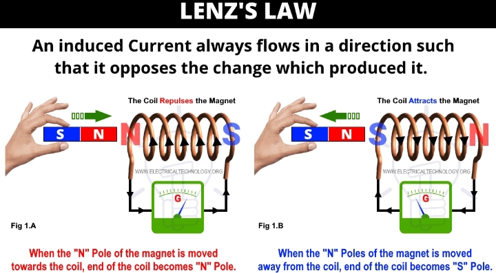
State lenz’s law and faraday’s law of electromagnetic induction
Faraday’s law: First law states that whenever there is a change in the magnetic inclines in a circuit, there will always be an induced e.m.f in the circuit or whenever a conductor acts on magnetic flux or it’s cut by a magnetic flux, an e.mf is induced in that conductor.
Second law states that the magnitude of the induced e.m.f is directly proportional to the rate of change in magnetic flux( or magnetic lines) linking to the circuit.
State three (3) factors in which the force on a current carrying conductor in a magnetic field depends
I. Strength of magnetic field
II. Strength of electric conductor
III. Length of conductor
With the aid of suitable diagram, describe the magnetic field around a solenoid
Solenoid Is the number of a turns of wire wound in the same direction. All the turns in a solenoid are in the same direction so that they can assist one another passing a magnetic field. For instance if a rod of iron is inserted inside the solenoid, only the magnetic field becomes intensified.
The magnetic field inside a solenoid is proportional to both the current and the number of turns per unit length. There is no dependence on the diameter of the solenoid and the field strength does not depend on the position inside the solenoid i.e the field inside is constant.
- A conductor of active length 0.3m moves in a magnetic field at a linear velocity of 500m/s. If the magnetic flux density is 0.05T, calculate the average value of the induced e.m.f, if the direction of movement of the conductor is perpendicular to the field.
The average value of the induced e.m.f = magnetic flux density × length × velocity
Therefore e.m.f, E = BLV
B = 0.05T, L = 0.3m, velocity= 500m/s
0.3×0.05×500 = 7.5volts
- A coil of 1000 turns and length 0.2m carries a current of 5A. If the cross sectional area of the magnetic circuit is proportional to the flux 1.0cm² and the flux produced by the coil is 0.15mWb. Calculate the permeability of the magnetic material.
L = 0.2m, N = 1000 turns, I = 5A, A = 1.0cm² = 0.01m², ∅ = 0.15mWb
Length= L, number of turns= N, current= I, area = A, flux = 0.15×10–³Wb
∅ = BA; B = ∅/A; B = 0.00015/0.01
Flux density, B = 0.015wb/m²
Magnetic field=H
H = IN/L
(5 × 1000) ÷ 0.2 = 25,000A/m
Calculate the permeability of the magnetic material
Permeability of the magnetic material = flux density/ magnetic field
B/H = 0.015/25000
6 × 10–⁷ Tesla/Ampere meter
(III) Magnemotive force (M.M.F)
This is the flux which drives magnetic flux through a magnetic circuit ( i.e the route or path which is followed by magnetic flux ) and correspond to electromagnetic force (e.m.f) in any electric circuit. It is usually measured in Ampere turns
F = IN
where F = Magnemotive force
I = current
N = number of turns

