
Introduction to Fault analysis in power system
A fault is any abnormal condition in a power system. The steady state operating mode of a
power system is balanced 3-phase a.c. .However, due to sudden external or internal
changes in the system, this condition is disrupted.
When the insulation of the system fails at one or more points or a conducting object
comes into contact with a live point, a short circuit or a fault occurs.
CAUSES OF POWER SYSTEM FAULTS
- Lightning
- Heavy winds
- Trees falling across lines
- Vehicles colliding with towers or poles
- Birds shorting lines
- Aircraft colliding with lines
- Vandalism
- Small animals entering switchgear
- Line breaks due to excessive loading
COMMON POWER SYSTEM FAULTS
Power system faults may be categorised as one of four types; in order of frequency of
occurrence, they are: - Single line to ground fault
- Line to line fault
- Double line to ground fault
- Balanced three phase fault
The first three types constitutes severe unbalanced operating conditions which involves only
one or two phases hence referred to as unsymmetrical faults. In the fourth type, a fault
involving all the three phases occurs therefore referred to as symmetrical (balanced) fault.
- A positive sequence set of three symmetrical voltages (i.e. all numerically equal
and all displaced from each other by 1200) having the same phase sequence abc as the
original set and denoted by Va1,Vb1,Vc1 - A negative sequence set of three symmetrical voltages having the phase sequence
opposite to that of the original set and denoted by Va2, Vb2, Vc2 - A zero sequence set of three voltages, all equal in magnitude and in phase with each other
and denoted by Va0, Vb0, Vc0 as shown in fig (1c) below:
Va0
The causes of faults are numerous, e.g.
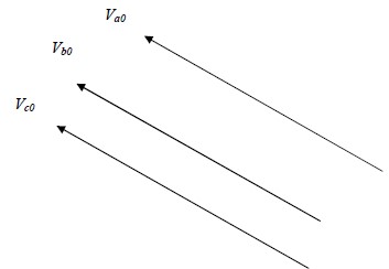
The positive, negative and zero sequence sets above are known as symmetrical components.
Thus we have,
Va = Va1 +Va2 +Va0
Vb = Vb1 +Vb2 +Vb0
Vc = Vc1 + Vc2 +Vc0
The symmetrical components application to power system analysis is of fundamental
importance since it can be used to transform arbitrarily unbalanced condition into symmetrical
components, compute the system response by straightforward circuit analysis on simple
circuit models and transform the results back to the original phase variables.
Generally the subscripts 1, 2 and 0 are used to indicate positive sequence, negative sequence
and zero sequence respectively.
The symmetrical components do not have separate existence; they are just mathematical
components of unbalanced currents (or voltages) which actually flow in the system.
1.2.2 The “a” operator
The operator “a” as used in symmetrical components is one in which when multiplied to a
vector, rotates the vector through 1200 in a positive (anticlockwise) direction without
changing the magnitude.
The operator “a” is defined as 1 1200
THREE-SEQUENCE IMPEDANCES AND SEQUENCE NETWORKS
Positive sequence currents give rise to only positive sequence voltages, the negative sequence
currents give rise to only negative sequence voltages and zero sequence currents give rise to
only zero sequence voltages, hence each network can be regarded as flowing within in its own
network through impedances of its own sequence only.
In any part of the circuit, the voltage drop caused by current of a certain sequence depends on
the impedance of that part of the circuit to current of that sequence.
The impedance of any section of a balanced network to current of one sequence may be
different from impedance to current of another sequence.
The impedance of a circuit when positive sequence currents are flowing is called impedance,
When only negative sequence currents are flowing the impedance is termed as negative
sequence impedance.
With only zero sequence currents flowing the impedance is termed as zero sequence
impedance.
The analysis of unsymmetrical faults in power systems is carried out by finding the
symmetrical components of the unbalanced currents. Since each sequence current causes a
voltage drop of that sequence only, each sequence current can be considered to flow in an
independent network composed of impedances to current of that sequence only.
The single phase equivalent circuit composed of the impedances to current of any one
sequence only is called the sequence network of that particular sequence.
The sequence networks contain the generated emfs and impedances of like sequence.
Therefore for every power system we can form three- sequence network s. These sequence
networks, carrying current Ia1, Ia2 and Ia0 are then inter-connected to represent the different
fault conditions.
PHYSICAL SIGNIFICANCE OF SEQUENCE COMPONENTS
8This is achieved by considering the fields which results when these sequence voltages are
applied to the stator of a 3-phase machine e.g. an induction motor.
If a positive sequence set of voltages is applied to the terminals a, b, c of the machine, a
magnetic field revolving in a certain direction will be set up. If now the voltages to the
terminals band c are changed by interchanging the leads to terminals b and c, it is known from
induction motor theory that the direction of magnetic field would be reversed.
It is noted that for this condition, the relative phase positions of the voltages applied to the
motor are the same as for the negative sequence set.
Hence, a negative sequence set of voltages produces a rotating field rotating in an opposite
direction to that of positive sequence.
For both positive and negative sequence components, the standard convention of counter
clockwise rotation is followed.
The application of zero sequence voltages does not produce any field because these voltages
are in phase and the three -phase windings are displaced by 1200.The positive and the
negative sequence set are the balanced one. Thus, if only positive and negative sequence
currents are flowing, the phasor sum of each will be zero and there will be no residual current.
However, the zero sequence components of currents in the three phases are in phase and the
residual current will be three times the zero sequence current of one phase. In the case of a
fault involving ground, the positive and negative sequence currents are in equilibrium while
the zero sequence currents flow through the ground and overhead ground wires.
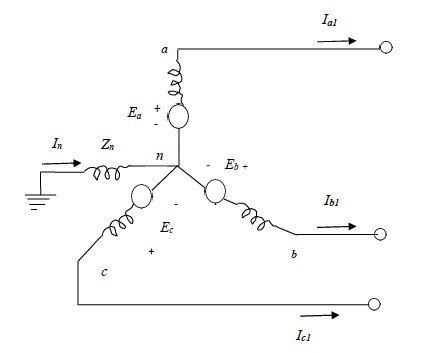
SEQUENCE NETWORKS OF SYNCHRONOUS MACHINES
An unloaded synchronous machine having its neutral earthed through impedance, zn, is shown
in fig. 2(a) below.
A fault at its terminals causes currents Ia, Ib and Ic to flow in the lines. If fault involves earth, a
current In flows into the neutral from the earth. This current flows through the neutral
impedance Zn.
Thus depending on the type of fault, one or more of the line currents may be zero.
Positive sequence network
The generated voltages of a synchronous machine are of positive sequence only since the
windings of a synchronous machine are symmetrical.
The positive sequence network consists of an emf equal to no load terminal voltages and is in
series with the positive sequence impedance Z1 of the machine. Fig. next below shows
the paths for positive sequence currents and positive sequence network respectively on a
single phase basis in the synchronous machine. The neutral impedance Zn does not appear in
the circuit because the phasor sum of Ia1, Ib1 and Ic1 is zero and no positive sequence current
can flow through Zn. Since its a balanced circuit, the positive sequence N
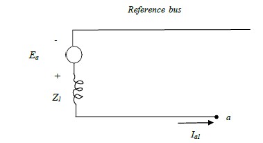
The reference bus for the positive sequence network is the neutral of the generator.
The positive sequence impedance Z1 consists of winding resistance and direct axis reactance.
The reactance is the sub-transient reactance X”d or transient reactance X’d or synchronous
reactance Xd depending on whether sub-transient, transient or steady state conditions are
being studied.
From fig. below, the positive sequence voltage of terminal a with respect to the reference bus is
given by:
Va1= Ea – Z1Ia1 Ia1
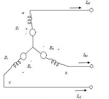
Fig.2 (b)
Negative sequence network
A synchronous machine does not generate any negative sequence voltage. The flow of
negative sequence currents in the stator windings creates an mmf which rotates at
synchronous speed in a direction opposite to the direction of rotor, i.e., at twice the
synchronous speed with respect to rotor.
Thus the negative sequence mmf alternates past the direct and quadrature axis and sets up a
varying armature reaction effect. Thus, the negative sequence reactance is taken as the
average of direct axis and quadrature axis sub-transient reactance, i.e.,
X2 = 0.5 ( X”d + X”q ).
It not necessary to consider any time variation of X2 during transient conditions because there
is no normal constant armature reaction to be effected. For more accurate calculations, the
negative sequence resistance should be considered to account for power dissipated in the rotor
poles or damper winding by double supply frequency induced currents.
The fig.2 (d) and fig.2 (e) shows the negative sequence currents paths and the negative
sequence network respectively on a single phase basis of a synchronous machine.
The reference bus for the negative sequence network is the neutral of the machine. Thus, the
negative sequence voltage of terminal a with respect to the reference bus is given by:
Va2= -Z2Ia2
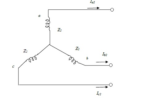
Fig.2 (d)
Reference bus
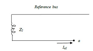
Fig.2 (e)
Zero sequence network
No zero sequence voltage is induced in a synchronous machine. The flow of zero sequence
currents in the stator windings produces three mmf which are in time phase. If each phase
winding produced a sinusoidal space mmf, then with the rotor removed, the flux at a point on
the axis of the stator due to zero sequence current would be zero at every instant.
When the flux in the air gap or the leakage flux around slots or end connections is considered,
no point in these regions is equidistant from all the three –phase windings of the stator.
The mmf produced by a phase winding departs from a sine wave, by amounts which depend
upon the arrangement of the winding.
The zero sequence currents flow through the neutral impedance Zn and the current flowing
through this impedance is 3Ia0.
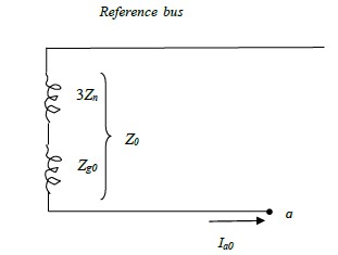
Fig.2(f) and fig.2(g) shows the zero sequence current paths and zero sequence network
respectively, and as can be seen, the zero sequence voltage drop from point a to ground is –
3Ia0Zn –Ia0Zg0 where Zg0 is the zero sequence impedance per phase of the generator.
Since the current in the zero sequence network is Ia0 this network must have an impedance of
3Zn +Zg0. Thus,
Z0 =3Zn +Zg0
The zero sequence voltage of terminal a with respect to the reference bus is thus:
Va0 = -Ia0Z0
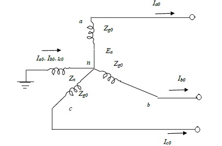
Fig.2 (f)
Reference bus
SEQUENCE IMPEDANCES OF TRANSMISSION LINE
The positive and negative sequence impedances of linear symmetrical static circuits do not
depend on the phase sequence and are, therefore equal. When only zero sequence currents
flow in the lines, the currents in all the phases are identical. These currents return partly
through the ground and partly through overhead ground wires.
The magnetic field due to the flow of zero sequence currents through line, ground and round
wires is very different from the magnetic field due to positive sequence currents. The zero
sequence reactance of lines is about 2 to 4 times the positive sequence reactance.
SEQUENCE IMPEDANCES OF TRANSFORMERS
A power system network has a number of transformers for stepping up and stepping down the
voltage levels.
A transformer for a 3-phase circuit may consist of three single phase transformers with
windings suitably connected in star or delta or it may be a 3-phase unit.
Modern transformers are invariably three-phase units because of their lower cost, lesser space
requirements and higher efficiency. The positive sequence impedance of a transformer equals
its leakage impedance. The resistance of the windings is usually small as compared to leakage
reactance.
For transformers above 1 MVA rating, the reactance and impedance are almost equal. Since
the transformer is a static device, the negative sequence impedance is equal to the positive
sequence impedance.
The zero sequence impedance of 3-phase units is slightly different from positive sequence
impedance. However the difference is very slight and the zero sequence impedance is also
assumed to be the same as the positive sequence impedance.
The flow of zero sequence currents through a transformer and hence in the system depends
greatly on the winding connections. The zero sequence currents can flow through the winding
connected in star only if the star point is grounded. If the star point isolated zero sequence
currents cannot flow in the winding.
The zero sequence currents cannot flow in the lines connected to a delta connected winding
because no return path is available for these zero sequence currents. However, the zero
sequence currents caused by the presence of zero sequence voltages can circulate through the
delta connected windings.
FORMATION OF SEQUENCE NETWORKS
A power system network consists of synchronous machines, transmission lines and
transformers.
The positive sequence network is the same as the single line reactance diagram used for the
calculation of symmetrical fault current. The reference bus for positive sequence network is
the system neutral.
The negative sequence network is similar to the positive sequence network except that the
negative sequence network does not contain any voltage source. The negative sequence
impedances for transmission line and transformers are the same as the positive sequence
impedances. But the negative sequence impedance of a synchronous machine may be
different from its positive sequence impedance.
Any impedance connected between a neutral and ground is not included in the positive and
negative sequence networks because the positive and the negative sequence currents cannot
flow through such impedance.
The zero sequence network also does not contain any voltage source. Any impedance
included between neutral and ground becomes three times its value in a zero sequence
network.
The following are the summary of the rules for the formation of sequence networks:-
- The positive sequence network is the same as single line impedance or reactance
diagram used in symmetrical fault analysis. The reference bus for this network is the
system neutral. - The generators in power system produce balanced voltages. Therefore only positive
sequence network has voltage source. There are no voltage sources in negative and
zero sequence networks. - The positive sequence current can cause only positive sequence voltage drop.
Similarly negative sequence current can cause only negative sequence voltage drop
and zero sequence current can cause only zero sequence voltage drop. - The reference for negative sequence network is the system neutral. However, the
reference for zero sequence network is the ground. Zero sequence current can flow
only if the neutral is grounded. - The neutral grounding impedance Zn appears as 3Zn in the zero sequence network.
- The three sequence networks are independent and are interconnected suitably
depending on the type of fault.
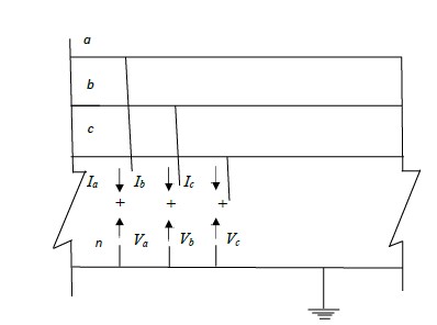
UNSYMMETRICAL FAULTS
The basic approach to the analysis of unsymmetrical faults is to consider the general situation
shown in the fig.3.0 which shows the three lines of the three- phase power system at the point
of fault.
The general terminals brought out are for purposes of external connections which simulate the
fault. Appropriate connections of the three stubs represent the different faults, e.g., connecting
stuba’ to ground produces a single line to ground fault, through zero impedance, on phasea’. The currents in stubs b and c are then zero and Ia is the fault current.
Similarly, the connection of stubs b and c produces a line to line fault, through zero
impedance, between phases b and c, the current in stub a is then zero and Ib is equal to Ic.The
positive assignment of phase quantities is important. It is seen that the currents flow out of
the system.
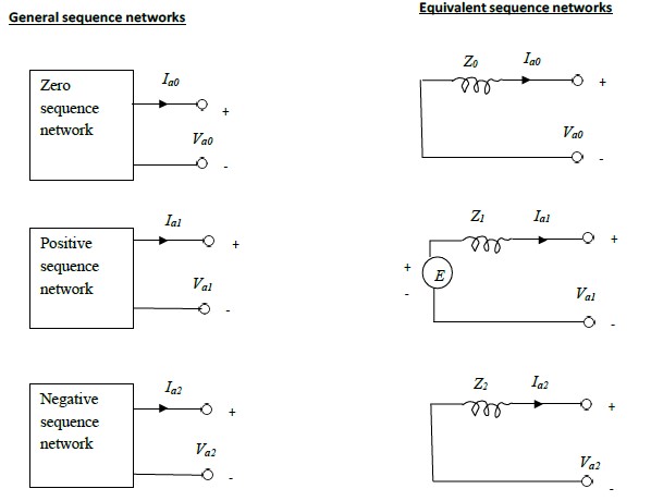
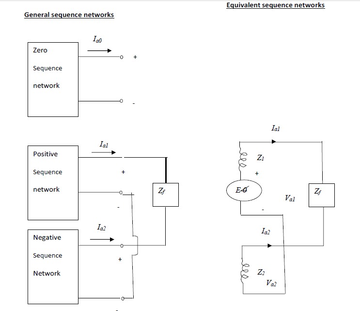
The three general sequence circuits are shown in fig.3.1 (a). The ports indicated correspond to
the general 3- phase entry port of fig.3.1. A suitable inter- connection of the three- sequence
networks depending on the type fault yields the solution to the problem.
The sequence networks of fig.3.1 (a) can be replaced by equivalent sequence networks of
fig.3.1 (b) . Z0, Z1 and Z2 indicate the sequence impedances of the network looking into the
fault
SINGLE LINE TO GROUND FAULT
The termination of the three- phase access port as shown in fig. 3.2 brings about a condition
of single line to ground fault through a fault impedance Zf .
Typically Zf is set to zero in all fault studies. I include Zf in the analysis for the sake of
generality. The terminal conditions at the fault point give the following equations:
Ib = 0
Ic = 0
Va = IaZf
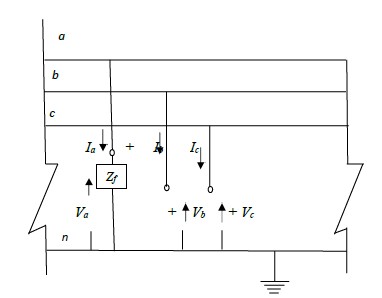
Fig. 3.2
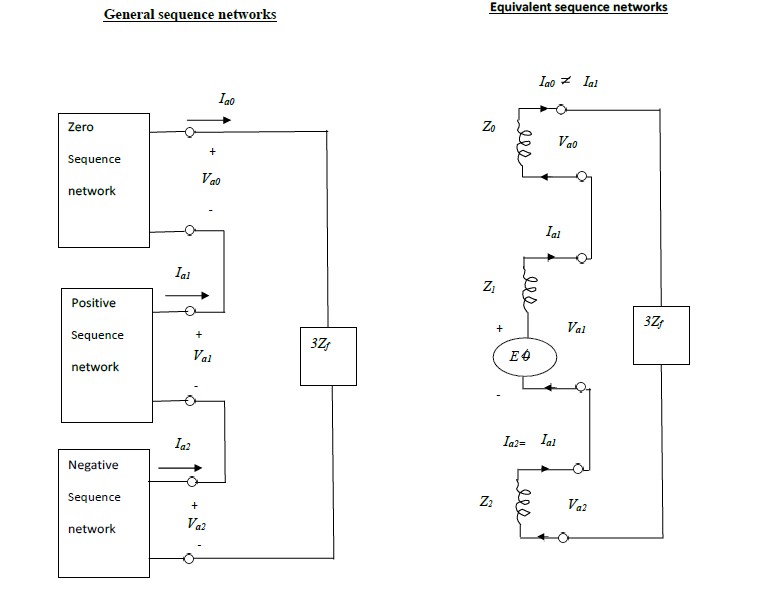
Connections of sequence networks for a single line to ground fault and its simplified
equivalent circuit are shown in the fig. 3.3(a) and fig. 3.3 (b) below:
The
+
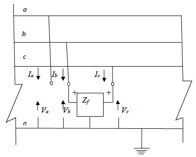
LINE TO LINE FAULT
The termination of the three- phase access port as in the fig.3.4 below simulates a line to line fault through a fault impedance Zf.
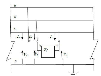
Fig. 3.4
The terminal conditions at the fault point give the following equations,
Ia = 0
Ib = -Ic
Vb = Vc + Zf Ib
Ib = -Ic = Ia0 + a2Ia1 + aIa2
Connection of sequence networks for a line to line fault and its simplified equivalent circuit
are shown in the fig.3.5 (a) and fig.(b) below.
DOUBLE LINE TO GROUND FAULT
The termination of the three- phase access port as shown in fig.3.6 simulates a double line to ground fault through fault impedance Zf.
The terminal conditions at the fault point give the following equations,
The sequence networks and the equivalent circuit are shown by the Fig.3.7 (a) and Fig. 3.7 (b)
below
BALANCED THREE PHASE FAULT
This type of fault occurs infrequently, as for example, when a line, which has been made safe for
maintenance by clamping all the three phases to earth, is accidentally made alive or when, due to
slow fault clearance, an earth fault spreads across to the other two phases or when a mechanical
excavator cuts quickly through a whole cable.
It is an important type of fault in that it results in an easy calculation and generally, a pessimistic
answer.
The circuit breaker rated MVA breaking capacity is based on 3- phase fault MVA. Since circuit
breakers are manufactured in preferred standard sizes e.g. 250, 500, 750 MVA high precision is not
necessary when calculating the 3- phase fault level at a point in a power system.
The system impedances are also never known accurately in three phase faults.
Power System -III
R20A0209
UNIT-IV
LOAD FLOW STUDIES-1
REVIEW OF NUMERICAL SOLUTION OF EQUATIONS
The numerical analysis involving the solution of algebraic simultaneous equations forms
the basis for solution of the performance equations in computer aided electrical power
system analyses, such as during linear graph analysis, load flow analysis (nonlinear
equations), transient stability studies (differential equations), etc. Hence, it is necessary to