
B
What is Data Communication?
Data communication refers to the exchange of data between a source and a receiver via form of transmission media such as a wire cable. Data communication is said to be local if communicating devices are in the same building or a similarly restricted geographical area.
The meanings of source and receiver are very simple. The device that transmits the data is known as source and the device that receives the transmitted data is known as receiver. Data communication aims at the transfer of data and maintenance of the data during the process but not the actual generation of the information at the source and receiver.
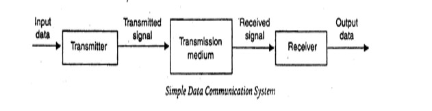
Datum mean the facts information statistics or the like derived by calculation or experimentation. The facts and information so gathered are processed in accordance with defined systems of procedure. Data can exist in a variety of forms such as numbers, text, bits and bytes. The Figure is an illustration of a simple data communication system
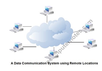
The term data used to describe information; under whatever form of words, you will be using. A data communication system may collect data from remote locations through data transmission circuits, and then outputs processed results to remote locations. Figure provides a broader view of data communication networks. The different data communication techniques which are presently in widespread use evolved gradually either to improve the data communication techniques already existing or to replace the same with better options and features. Then, there are data communication jargons to contend with such as baud rate, modems, routers, LAN, WAN, TCP/IP, ISDN, during the selection of communication systems. Hence, it becomes necessary to review and understand these terms and gradual development of data communication methods.
Components of data communication system
1. Message: It is the information or data to be communicated. It can consist of text, numbers, pictures, sound or video or any combination of these.
2. Sender: It is the device/computer that generates and sends that message.
3. Receiver: It is the device or computer that receives the message. The location of receiver computer is generally different from the sender computer. The distance between sender and receiver depends upon the types of networks used in between.
4. Medium: It is the channel or physical path through which the message is carried from sender to the receiver. The medium can be wired like twisted pair wire, coaxial cable, fiber-optic cable or wireless like laser, radio waves, and microwaves.
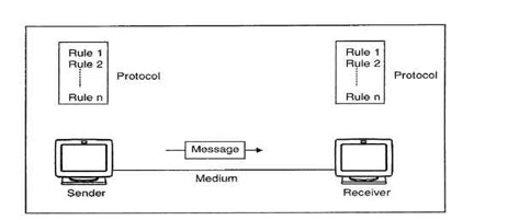
5. Protocol: It is a set of rules that govern the communication between the devices. Both sender and receiver follow same protocols to communicate with each other.
A protocol performs the following functions:
1. Data sequencing. It refers to breaking a long message into smaller packets of fixed size. Data sequencing rules define the method of numbering packets to detect loss or duplication of packets, and to correctly identify packets, which belong to same message.
2. Data routing. Data routing defines the most efficient path between the source and destination.
3. Data formatting. Data formatting rules define which group of bits or characters within packet constitute data, control, addressing, or other information.
4. Flow control. A communication protocol also prevents a fast sender from overwhelming a slow receiver. It ensures resource sharing and protection against traffic congestion by regulating the flow of data on communication lines.
5. Error control. These rules are designed to detect errors in messages and to ensure transmission of correct messages. The most common method is to retransmit erroneous message block. In such a case, a block having error is discarded by the receiver and is retransmitted by the sender.
6. Precedence and order of transmission. These rules ensure that all the nodes get a chance to use the communication lines and other resources of the network based on the priorities assigned to them.
7. Connection establishment and termination. These rules define how connections are established, maintained and terminated when two nodes of a network want to communicate with each other.
8.Data security. Providing data security and privacy is also built into most communication software packages. It prevents access of data by unauthorized users.
9. Log information. Several communication software is designed to develop log information, which consists of all jobs and data communications tasks that have taken place. Such information may be used for charging the users of the network based on their usage of the network resources.
The effectiveness depends on four fundamental characteristics of data communications.
1. Delivery: The data must be delivered in correct order with correct destination.
2. Accuracy: The data must be delivered accurately.
3. Timeliness: The data must be delivered in a timely manner. late delivered Data useless.
4. Jitter: It is the uneven delay in the packet arrival time that cause uneven quality.
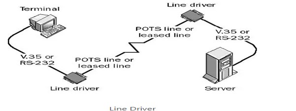
Line Driver
Line Driver is a device that can use installed twisted-pair phone lines or leased lines to connect terminals to servers in different parts of a building or in different buildings.
A line driver is essentially a combination of a signal converter and an amplifier for digital signals. The signal converter performs line conditioning, and the amplifier increases the signal strength.
Also called a “short-haul” device, a line driver allows a signal produced by a serial transmission device using an interface such as RS-232 to be carried over a longer distance than the interface standard allows, which for RS-232 is only 15 meters.
How it works
Line drivers are always used in pairs. One line driver is placed at the local site and is connected to the terminal, while the other is located at the remote site and is connected to the server. Line drivers are typically used to extend the maximum distance of serial communication protocols such as RS-232, V.35, X.21, and G.703 and can provide either synchronous or asynchronous communication in various vendor implementations. Considerations for line driver type include full-duplex or half-duplex communication, 2-wire or 4-wire cabling options, and various kinds of connectors.
The most common type of line driver uses an RS-232 serial interface for synchronous transmission of data over installed 4-wire telephone cabling. These line drivers can extend the maximum distance of RS-232 serial transmission from 15 meters to several kilometers.
For intrabuilding connections using line drivers, copper unshielded twisted-pair cabling or the installed telephone lines are typically used. For interbuilding connections, fiber-optic cabling is preferred
Line drivers are available for almost every kind of communication mode, from 19.2-Kbps RS-232 serial line drivers over 6 kilometers to 2-Mbps single-mode fiber-optic line drivers over 18 kilometers. Line drivers for parallel connections can extend parallel transmission of data from about 6 meters to several kilometers. Line drivers are also used in implementation of T1 lines.
Line drivers extend the transmission distance between terminals or computers connected along private lines or networks. They improve connectivity across local area networks (LAN), two-wire and four-wire copper telephone lines, and leased T1 or T3 connections. Some line drivers are called short haul modems because they facilitate xDSL, VDSL, and G.SHDLS transmissions. The term xDSL refers to a family of technologies such as symmetric digital subscriber line (SDSL) and asymmetric digital subscriber line (ADSL). SDSL uses the same data rates for upstream and downstream traffic. ADSL uses different rates for each type of traffic. Very-high bit-rate digital subscriber lines (VDLS) can transmit data as far as 50 m at speeds up to 26 Mbps. G.SHDSL or G.991.2 line drivers use a form of symmetric DSL developed by the International Telecommunications Union (ITU), an organization formerly known as the CCI
How to Select a Line Driver
Selecting line drivers requires an analysis of performance specifications, mounting styles, form factors, and special features. Performance specifications include supply voltage, data rate, propagation delay, pulse skew, transmission time, channel-to-channel skew, harmonic distortion and jitter. Some line drivers mount in telecommunications racks. Others are designed to stand alone or have an integrated circuit (IC) form factor. Typically, line driver features are a function of the larger communications infrastructure. For example, fiber optic networks provide data security, total electrical isolation, lightning and surge protection, and immunity from electromagnetic interference (EMI) and radio frequency interference (RFI).
Different Form Factors and Technology Families
Line drivers with an integrated circuit (IC) form factor differ in terms of logic family and package type. Logic families for line drivers include complementary metal-oxide semiconductor (CMOS,) emitter coupled logic (ECL), and low voltage differential signaling (LVDS). CMOS uses a combination of p-type and n-type metal-oxide-semiconductor field effect transistors (MOSFET). ECL also uses transistors, but to steer current through gates that compute logical functions. Low voltage differential signaling (LVDS) line drivers provide low skew, differential signaling, and speeds up to 1350 MHz. Package types for line drivers include small outline integrated circuit (SOIC) and quad flat package (QFP).
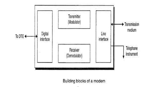
Modem:
Modem is abbreviation for Modulator – De-modulator. Modems are used for data transfer from one computer network to another computer network through telephone lines. The computer network works in digital mode, while analog technology is used for carrying massages across phone lines. Modulator converts information from digital mode to analog mode at the transmitting end and de-modulator converts the same from analog to digital at receiving end. The process of converting analog signals of one computer network into digital signals of another computer network so they can be processed by a receiving computer is referred to as digitizing.
When an analog facility is used for data communication between two digital devices called Data Terminal Equipment (DTE), modems are used at each end. DTE can be a terminal or a computer.
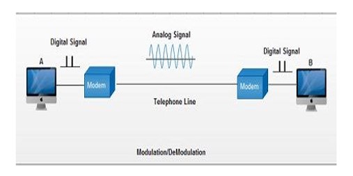
The modem at the transmitting end converts the digital signal generated by DTE into an analog signal by modulating a carrier. This modem at the receiving end demodulates the carrier and hand over the demodulated digital signal to the DTE.
The transmission medium between the two modems can be dedicated circuit or a switched telephone circuit. If a switched telephone circuit is used, then the modems are connected to the local telephone exchanges. Whenever data transmission is required connection between the modems is established through telephone exchanges.
Types of Modems
1. Cable Modems
Cable modems enable communication between your computer and ISP over a landline connection. These are a type of modem that allows access to high-speed data through a cable TV (CATV) network. They are external devices that are connected to your PC through a standard 10 BASE-T ethernet card and with twisted pair wiring.
2. Telephone Modems
These network devices allow data communication between two computers over the voice-grade telephone line. These are used for converting bits to analog signals to allow transmission through physical channels. They also convert analog signals in local loops to bits that are understandable by computer.
3. Digital Subscriber Line (DSL)
They are used for transmitting digital data over telephone lines. Such modems provide high-speed internet connection via telephone lines. Asymmetric and symmetric DSL are the two types of DSL. These modems use the existing telephone wiring of your home wiring which makes them cost-effective.
Relation between Modem and Router
The modem receives information from ISP over optical fiber, coaxial cable or phone lines, and then, it converts them into digital signals. Router pushes these signals to connect dives through either Wi-Fi or ethernet cables. The modem works as a translator since router and ISP transfer different signals and cannot communicate directly.
Data Terminal Equipment ( DTE )
Data Terminal Equipment is equipment which acts as source or destinations in digital communication and which is capable of converting information to signals and also reconverting received signals. Pieces of data terminal equipment usually do not communicate between each other, which is usually done by data communications equipment. Common examples of data terminal equipment: printers, routers, application servers etc.
Features of Data Terminal Equipment:
- With the help of link protocol, provides the data communication control function to the digital data communication.
- It can be single piece equipment or multiple pieces interconnected to perform the required functions.
- In most communications, data terminal equipment is the terminal.
- One of the key differences between data terminal equipment and data communications equipment is in the manner the connectors are wired.
- The universal asynchronous receiver transmitter in data terminal equipment performs error detection and clocking. Error detection helps in ensuring the data sent is free of corruption. Clocking helps in ensuring the data is sent at the right rate of receiving at the destination.
- In most cases, data terminal equipment is a device which uses serial transmission to transmit data, which is done with help of the serial port in the device. It usually implements a male connector.
- To connect a data terminal equipment to a communication link, data communication equipment needs to be used.
Data Communications Equipment (DCE)
It is also called Data Circuit-Terminating Equipment. At the physical layer, the function of DCE is that it supplies that clocking. DCE provides the service. The DCE has devices whose function is to put data on the local loop. As its function, the DCE provides an interface for connecting subscribers to a communication link on the WAN cloud. Its function is to establish, maintain, and terminate communication network sessions between a data source and its destination.
DCE examples include ISDN adapters, Satellites (including base stations) Microwave stations, NIC (network interface cards) etc.
Given below is the diagram for DTE and DCE −
Differences between DTE and DCE
The major differences between DTE and DCE are as follows−
| DTE | DCE |
| DTE is the acronym for Data Terminal Equipment | DCE is the acronym for Data Communications Equipment |
| DTE is to look for clocking. | DCE supplies that clocking. |
| Devices included in DTE are routers and computers. | Devices included in DCE are modem. |
| There should be no coordination between DTE devices. | Coordination should be required between DCE devices to communicate. |
| Examples − printers, computer, file servers. | Examples − Satellites, ISDN adapters, NIC. |
Clusters.
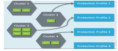
A Cluster is a set of identically configured Defense devices. When you create a new Cluster, you must associate it with a Protection Profile; this Protection Profile contains a Policy which controls how the devices in that Cluster respond to traffic. A single Smart Wall Central Management Server (CMS) can control up to 16 Clusters. After installation, the CMS initially has a single default Cluster which is associated with the default Protection Profile and default Authentication Group.
Cluster
How you choose to group your Defense devices depends on your deployment:
- If you want to use multiple Protection Profiles (to have some Defense devices treat traffic differently to others), you need to have a new Cluster for each Protection Profile you want to use.
- If you want to use a single Protection Profile for all your Defense devices, you may choose to have a single Cluster. However multiple Clusters can use the same Protection Profile, so you could continue to use a single Protection Profile while you group your devices into logical arrangements, such as by location or link type. Having devices grouped in that way can improve the usefulness of SmartWall SecureWatch.
- Or you may choose a mixture of both, using multiple Protection Profiles where each has multiple Clusters. However, a Cluster can only be associated with one Protection Profile at a time. A Defense device can only belong to one Cluster at a time. If you want to move a Defense device to a new Cluster, you must first remove it from the current Cluster before you can add it to the new one.
Deployment Options and Clusters
There are multiple ways to deploy your Defense devices to provide the best DDoS mitigation for your network. The two most common are:
- Inline DDoS Mitigation – The Defense devices are deployed physically inline on the incoming fiber connection, in front of your edge router.
- Scrubbing DDoS Mitigation – Traffic requiring DDoS protection is logically rerouted by your router through the Defense devices.
Cluster Devices.
There are 2 types of SmartWall device which you can manage in the CMS:
- Defense device – This can be a physical device (NTD120, NTD280, or NTD1100) or a virtual device (vNTD). It uses an attack mitigation policy to determine what traffic is allowed through to your internal network.
- Bypass device – This is a physical device which can re-route traffic to bypass the Defense device and send all traffic to your internal network. Bypass devices are connected to a Segment on a Defense device.
1. Defense Device Types
There are four Defense device models you can deploy with this version of the SmartWall Threat Defense System:
- NTD1100 – A physical Defense device which protects 100Gbit Ethernet links. This device can optionally include an internal bypass capability (NTD1100-zpb).
- NTD280 – A physical Defense device which protects up to eight 10Gbit Ethernet links.
- NTD120 – A physical Defense device which protects up to two 10Gbit Ethernet links.
- vNTD (NTD Virtual Edition ) – A virtual Defense device deployed on your own ESXi or KVM serve, with up to 10Gbit throughput per device. Each vNTD device must be licensed in the CMS.
Specific settings for Defense device types
Some settings only affect specific types of Defense devices:
- NTD120 – Load Balancing (Advanced Settings) only affects NTD120 devices.
- vNTD – As the vNTD is not a physical device each new deployment must be licensed by Corero before it is recognized by the CMS. Learn more about licensing.
- NTD1100 – Set Ethernet modes for interfaces. For an NTD1100 with internal bypass (NTD-zpb), you can set Bypass Operating mode overrides for the device.
2. Bypass Device Types
There are two types of Bypass device you can use with the SmartWall Threat Defense System:
- External Bypass device – A physical external bypass device which is physically connected to a Segment on a Defense device. For 10Gbit links, the SmartWall Network Bypass Appliance (NBA) is recommended. If you have a 100Gbit Defense device without an internal bypass, you can use a third-party 100Gbit bypass device. Third-party 100Gbit bypass devices cannot be managed from within the CMS; you must SSH to their own management portal to change the Bypass Mode.
- Internal Bypass – An Internal Bypass card which can be delivered as part of an NTD1100. The Internal Bypass can be managed from the CMS in exactly the same way as an NBA.
Network Node
A network node can be defined as the connection point among network devices such as routers, printers, or switches that can receive and send data from one endpoint to the other.
Types of network nodes
The network is used to exchange, store, send, and retrieve data between network devices, also known as network nodes. Each network node acts as a connection point for data transmission, process recognition, packet switching, and network distribution. Generally, nodes are programmed to identify, process, and transmit data from one node to another. They can perform several functions based on the application and network. In a network, multiple nodes are used. A node can be a computer, printer, switch, or router. Nodes highly depend on the referred network and protocol layer to form a network connection. Additionally, each node on a network includes a unique IP address.
Nodes in a threaded environment can be divided into two roles:
- Routers: The role of a router node is to transmit packets from network devices. It helps maintain easy and quick connections between devices struggling to connect to the network and offers safe commissioning services.
- End device: The role of an end device is to connect and interact with a router.
Outlined below are the different types of network nodes based on the application and function in a distributed network.
- Internet network nodes: The host computers are referred to as the physical network nodes in internet networks. These nodes can be recognized with the help of their unique IP addresses; however, some data link equipment doesn’t include an IP address, such as WLAN access points.
- Data communication nodes: Data communication devices are physical nodes or communication devices such as switches, routers, hubs, bridges, modems, and more. These nodes are located between data communication circuits and Data Terminal Nodes (DTE), and the major role of these devices is to perform signal conversion, coding, and line clocks. Devices such as host computers, digital telephones, printers, and servers act as DTE.
- Telecommunications: Telephone nodes can include a computer that provides intelligent network services or private or public telephones capable of exchanging information. Nodes in cellular networks have base station controllers. The primary function of these controllers is to control multiple base stations.
- LANs and WANs: LANs and WANs consist of physical nodes or devices and include a unique MAC address for Network Interface Card (NIC). Such network devices include computers, wireless LAN access points, modems, and more.
- Distributed nodes: Distributed nodes refer to the nodes involved in a distributed network environment. They can be physical or virtual nodes and are used to maintain transparency within the network.
Network nodes examples.
Switches: The network devices that follow the OSI model to send and receive data packets over the network are known as switches. Multiple devices such as computers, printers, and modems can be plugged in a single switch with multiple ports. Switches can examine destination addresses and perform error checking during data transmission. They support all modes of communication, including unicast, broadcast, and multicast and use packet-switching technology to send and receive the data from source to destination. Additionally, switches can manage networks.
There are four types:
- Managed switches
- Unmanaged switches
- PoE switches
- LAN switches
- Other examples of network nodes: a computer, printer, or router. How to map network nodes
Benefits of using network mapping tools:
- Network mapping tools can automatically discover network topology or devices on a network using protocols such as ICMP, SNMP, CDP, and more.
- They can build multiple maps to save bandwidth, resources, and time.
- They can auto-detect and monitor new devices and unknown systems to maintain up-to-date and accurate records.
- They can maintain multiple network maps to help you demonstrate compliance with regulatory needs such as PCI, HIPAA, SOX, and more.
MODULATION
When the message signal is superimposed on the carrier signal, it is known as modulation. The message signal is superimposed on the top of the carrier wave. Here, superimposed means placing a signal on the other signal. The resultant signal formed has improved frequency and strength. The translation of the signal is required at the transmitter end for both the analog and digital signals. The translation is carried out before the signal is brought on the channel for transmission to the receiver. . In communication system, the message or the information signal is converted to the electronic signal, which is transmitted through the communication channel to the receiver. The receiver performs the demodulation process and converts the electronic signal back into its original form.
Message signal
The original signal that contains a message to be transmitted to the receiver is known as message signal. A message signal contains information or a message. It is the original signal that needs to be transmitted from the transmitter to the receiver. The transmitter converts the signal into a suitable form and sends it through the communication channel to the receiver. The communication channel is a medium for the signal to travel from one end to the other. The receiver perceives the signal, which is converted back to its original form. A message signal suffers from attenuation and various noise factors. It is essential to modulate the message signal to remove the noise. It also helps in improving the efficiency of the signal. Hence, a message signal is often known as a modulated signal. Another name of the message signal is the baseband signal.
Carrier signal
A carrier signal is a signal with a constant frequency, which is generally high. The carrier signal waves do not require a medium to propagate The carrier signal and the message signal share the same medium of propagation. It also allows carriers of different frequencies to transmit, which gives rise to multiplexing, the method to transmit multiple signals effectively over the same communication channel. The high-frequency carrier is also used in various modulation processes because it travels with high speed and allows the message signal to travel long distances. If the carrier is suppressed during the modulation for improved efficiency, it can be further added afterward. This technique is known as the coherent detection method and is commonly used in amplitude modulation techniques, such as DSBSC (Double Sideband Suppress Carrier Modulation), SSBSC (Single Sideband Suppress Carrier Modulation), and VSBSC (Vestigial Sideband Suppress Carrier Modulation).
Baseband signal
A message signal that represents the band of frequencies is known as a baseband signal. The range of baseband signals is from 0 Hz to the cut-off frequency. It is also called an unmodulated signal or low-frequency signal.
Analog signal
An Analog signal is the output of a light/sound wave converted to an electrical signal.
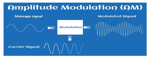
Amplitude Modulation (AM)
Modulation is the process of increasing and enhancing the frequency and strength of the message signal. It is the process that superimposes the original signal and the continuous high-frequency signal. In Amplitude Modulation (AM), the amplitude of the carrier wave is varied with the message signal. The process of AM is shown in the below image:

For example,
Audio Signal
The audio signals are the signals with high noise. It isn’t easy to transmit such signals over long distances. Hence, Modulation of audio signals is necessary for successful transmission. AM modulation is a process in which a message signal is superimposed on the radio wave as the carrier signal. It is combined with the radio carrier wave of high amplitude, which increases the magnitude of the audio signal.
Analog refers to the continuous variation with time. We can define analog communication and analog signal as:: An analog communication is a communication that continuously varies with time. It was discovered before digital communication. It requires less bandwidth for transmission with low-cost components. An analog signal is a signal that continuously varies with time. The examples of analog signal include sinusoidal waves and square waves.
A simple analog signal is shown below:
Types of Amplitude Modulation
The types of modulation are designated by the ITU (International Telecommunication Union). There are three types of Amplitude Modulation, which are as follows:
- Single Sideband Modulation
- Double Sideband Modulation
- Vestigial Sideband Modulation
The original name of the AM was DSBAM (Double Side Band Amplitude Modulation) because the side bands can appear on either side of the carrier frequency.
Single Sideband Modulation (SSB)
The SSB AM is the standard method to produce sidebands on only one side of the carrier frequency. The Amplitude Modulation can produce sidebands on both sides of the carrier frequency. In SSB, it uses bandpass filters to discard one sideband. The SSB modulation process improves the bandwidth utilization and total transmission power of the transmission medium.
Double Sideband Suppressed Carrier Modulation (DSB-SCB)
Double means two sidebands. The frequencies produced by the AM in DSB are symmetrical about the carrier frequency. The DSB is further categorized as DSB-SC and DSB-C. The DSB-SC (Double Sideband Suppress Carrier) modulation does not contain any carrier band, due to which its efficiency is also maximum as compared to other types of modulation. The carrier part in the DSB-SC is removed from the output component. The DSB-C (Double Sideband with Carrier) consists of the carrier wave. The output produced by the DSB-C has a carrier in combination with the message and the carrier component.
Vestigial Sideband Modulation (VSB)
Some of the information is SSB, and DSB may get lost. Hence, VSB is used to overcome the drawbacks of these two types of AM. Vestige means a section of the signal. In VSB, a section of the signal is modulated.
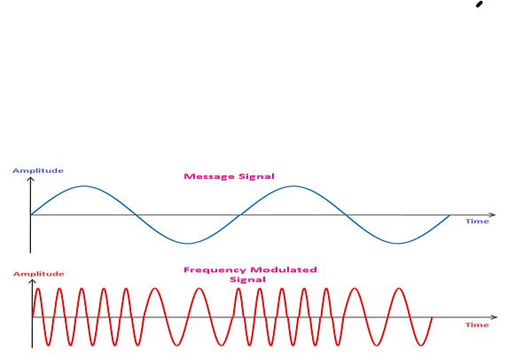
Frequency Modulation (FM)
When the frequency of the carrier wave varies with the amplitude of the message signal, it is called frequency modulation. It is a type of angle modulation, a non-linear modulation process. The superimposition of the two waves does not work in FM. The carrier signal is sent with the message signal during the modulation process. A message signal is also known as the baseband signal. It is nothing but a signal containing information that needs to be transmitted from the sender to the receiver. A sender in the communication system is known as a transmitter. Frequency Modulation is a modulation that operates in the region of high frequency and has high bandwidth. It operates in the VHF (Very High Frequency) range and can travel long distances. The FM modulated signal produces an infinite number of sidebands resulting in infinite bandwidth. FM has two types, Wideband FM and Narrowband FM. The Wideband FM has wider frequency bands with a wide range of frequencies, and narrowband FM has narrow bands operating in a short range of frequencies. Both have their applications and advantages. FM’s modulation and demodulation process are similar to the AM modulation and demodulation process except for the integrator and differentiator required to generate FM and PM signals. The information in FM is transmitted in the form of radio waves from the transmitter to the receiver.
The waveforms of the message signal and the FM signal are shown below:
Types of FM
In Double Sideband Amplitude Modulation, the two sidebands of frequencies ω + ωc and ω – ωc are produced. But FM generates infinite number of sidebands resulting in infinite bandwidth.
FM is categorized as:
- Narrowband Frequency Modulation
- Wideband Frequency Modulation
Narrowband Frequency Modulation
As the name implies, narrowband FM has narrow bandwidth. It occupies only a small portion of the FM signal and uses the small range of frequencies. The advantages of using Narrowband modulation are lower noise and improved sensitivity. Hence, it is commonly used in short distant communication and fixed location wireless transmission.
The modulating waveform in AM is given by:
V(t) = A[1 + m(t)] cosωct
Where,
A is the amplitude constant
ωc is the carrier frequency
m(t) is the message signal. It is the signal with finite energy.
The modulating waveform in FM is given by:
V(t) = Acosωct + Am(t)sinωct
If the message signal m(t) in FM is of finite energy, the spectral power densities of the both the Amplitude modulation and frequency modulation would be the same.
Wideband Frequency Modulation
As the name implies, wideband FM has wider bandwidth. It occupies a large portion of the FM signal and uses a wide range of frequencies. The advantage of using Wideband Frequency Modulation is its ability to transfer high data rates. Hence, it is commonly used in long-distance communication, broadcast FM stations, and quality radio transmission.
The parameter that determines the signal being Narrowband or Wideband is given by:
β = Δf / fm
Where,
fm is the modulated frequency
Δf is the frequency deviation
Β is the Bessel’s function
The signal is Narrowband if β << 1
The signal is Wideband if β >> 1
Applications of Frequency Modulation
- VHF Radio frequencies
FM is a high frequency modulation technique that is used in very high radio frequency transmission. It is also termed as radio broadcasting. Wideband FM was invented by an American engineer named Edwin Armstrong. He patented various receivers, such as heterodyne receiver (1918) and super-regenerative receiver in 1922. He also published various papers related to Frequency Modulation. - Magnetic tape storage
FM at intermediate frequencies is used to record black and white portions of the video signals. - Sound synthesis
FM is less susceptible to noise interference and popping sounds than AM. Hence, FM is suitable for sound broadcasting, commonly referred to as sound synthesis. The example includes analog TV sounds, speech, and music signals. - Telemetry
For telemetry, FDM (Frequency Division Multiplexing) is used to combine the group of the frequency modulated signal for transmission. It is the method to transmit one or more signals. Another technique apart from FDM is TDM (Time Division Multiplexing). - Two-way radio systems
The two-way radio communication system is based on the transmission and reception of the radio waves that travels at very high frequencies. Two-ways the quality of a system to both send and receive radio signals. - Video transmission system
The video system requires very low noise interference and high frequency for transmission upto long distances. Hence, it uses FM for transmission.
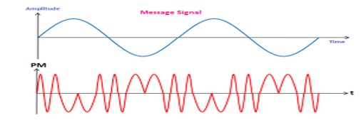
Phase Modulation
Phase modulation is defined as the process of varying the phase of the carrier signal linearly with the instantaneous value of the message signal. The waveforms of a message signal and the phase-modulated signal are shown below:
The equation of a PM signal is represented by:
V(t) = A cos [ωct + ϕ (t)]
Where,
ωc is the carrier frequency constant
A is the amplitude constant
ϕ (t) is the phase angle, which is not constant. It is a function of the baseband signal.
Let’s first discuss the message signal and the carrier signal..
Applications of Phase Modulation
The applications of Phase Modulation are listed as follows:
- Sound Synthesis
PM is less susceptible to noise interference and popping sounds than AM. Hence, it is suitable for sound broadcasting, commonly referred to as sound synthesis. - Digital Synthesizers
PM is used in digital synthesizers for the generation of signals and waveform. - Telephone communication
PM is widely used in telephone communication due to its high-speed transmission.
Advantages of Phase Modulation
The advantages of Phase Modulation are as follows:
- High speed
Phase modulation is considered as one the fastest modulation technique. It is due to the pulse generation at high speed. - Low signal power consumption
PM requires low signal power consumption due to its better efficiency and fast speed. - Simple circuit design
The components required in the phase modulated circuit are less as compared to FM. Hence, it has a simple circuit design. - Easy modulation and demodulation
Phase modulation and demodulation is easy as compared to PM due to its simple circuit design.
Disadvantages of Phase Modulation
- Low noise immunity
PM has less noise immunity than FM. It is because the frequencies are less affected by external disturbances than phase. Hence, PM has low noise immunity than FM. - Complex circuitry during conversion from FM to PM
The conversion process from frequency modulation to phase modulation is complex. It is due to the additional components required for the conversion. - Low signal to noise ratio
PM has a low signal to noise ratio than FM. It is due to the higher bandwidth of FM.
MULTIPLEXER
Multiplexing is a technique used to combine and send the multiple data streams over a single medium. The process of combining the data streams is known as multiplexing and hardware used for multiplexing is known as a multiplexer.
Multiplexing is achieved by using a device called Multiplexer (MUX) that combines n input lines to generate a single output line. Multiplexing follows many-to-one, i.e., n input lines and one output line.
De-multiplexing is achieved by using a device called De-multiplexer (DEMUX) available at the receiving end. DEMUX separates a signal into its component signals (one input and n outputs). Therefore, we can say that de-multiplexing follows the one-to-many approach.
- The transmission medium is used to send the signal from sender to receiver. The medium can only have one signal at a time.
- If there are multiple signals to share one medium, then the medium must be divided in such a way that each signal is given some portion of the available bandwidth. For example: If there are 10 signals and bandwidth of medium is100 units, then the 10 unit is shared by each signal.
- When multiple signals share the common medium, there is a possibility of collision. Multiplexing concept is used to avoid such collision.
- Transmission services are very expensive.
History of Multiplexing
- Multiplexing technique is widely used in telecommunications in which several telephone calls are carried through a single wire.
- Multiplexing originated in telegraphy in the early 1870s and is now widely used in communication.
- George Owen Squier developed the telephone carrier multiplexing in 1910.
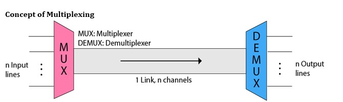
Concept of Multiplexing
- The ‘n’ input lines are transmitted through a multiplexer and multiplexer combines the signals to form a composite signal.
- The composite signal is passed through a Demultiplexer and demultiplexer separates a signal to component signals and transfers them to their respective destinations.
Advantages of Multiplexing:
- More than one signal can be sent over a single medium.
- The bandwidth of a medium can be utilized effectively.
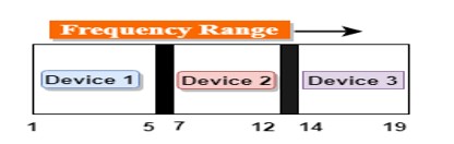
Frequency-division Multiplexing (FDM)
- It is an analog technique.
- Frequency Division Multiplexing is a technique in which the available bandwidth of a single transmission medium is subdivided into several channels.
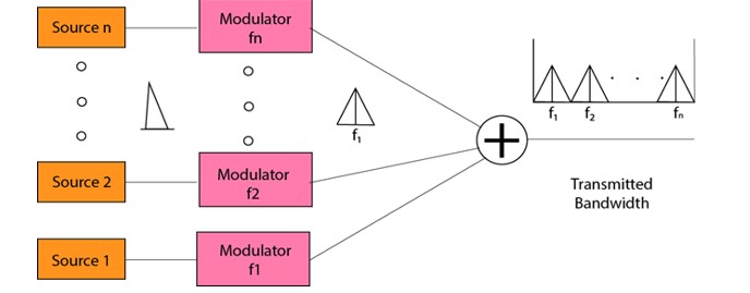
- In the above diagram, a single transmission medium is subdivided into several frequency channels, and each frequency channel is given to different devices. Device 1 has a frequency channel of range from 1 to 5.
- The input signals are translated into frequency bands by using modulation techniques, and they are combined by a multiplexer to form a composite signal.
- The main aim of the FDM is to subdivide the available bandwidth into different frequency channels and allocate them to different devices.
- Using the modulation technique, the input signals are transmitted into frequency bands and then combined to form a composite signal.
- The carriers which are used for modulating the signals are known as sub-carriers. They are represented as f1,f2..fn.
- FDM is mainly used in radio broadcasts and TV networks.
Advantages Of FDM:
- FDM is used for analog signals.
- FDM process is very simple and easy modulation.
- A Large number of signals can be sent through an FDM simultaneously.
- It does not require any synchronization between sender and receiver.
Disadvantages Of FDM:
- FDM technique is used only when low-speed channels are required.
- It suffers the problem of crosstalk.
- A Large number of modulators are required.
- It requires a high bandwidth channel.
Applications Of FDM:
- FDM is commonly used in TV networks.
- It is used in FM and AM broadcasting. Each FM radio station has different frequencies, and they are multiplexed to form a composite signal. The multiplexed signal is transmitted in the air.
Wavelength Division Multiplexing (WDM)
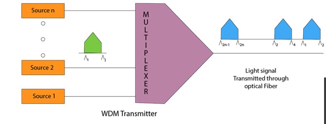
- Wavelength Division Multiplexing is same as FDM except that the optical signals are transmitted through the fibre optic cable.
- WDM is used on fibre optics to increase the capacity of a single fibre.
- It is used to utilize the high data rate capability of fibre optic cable.
- It is an analog multiplexing technique.
- Optical signals from different source are combined to form a wider band of light with the help of multiplexer.
- At the receiving end, demultiplexer separates the signals to transmit them to their respective destinations.
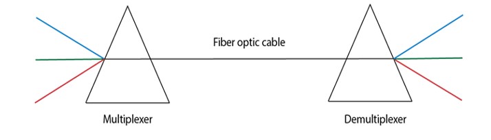
- Multiplexing and Demultiplexing can be achieved by using a prism.
- Prism can perform a role of multiplexer by combining the various optical signals to form a composite signal, and the composite signal is transmitted through a fibre optical cable.
- Prism also performs a reverse operation, i.e., demultiplexing the signal.
Time Division Multiplexing (TDM)
- It is a digital technique.
- In Frequency Division Multiplexing Technique, all signals operate at the same time with different frequency, but in case of Time Division Multiplexing technique, all signals operate at the same frequency with different time.
- In Time Division Multiplexing technique, the total time available in the channel is distributed among different users. Therefore, each user is allocated with different time interval known as a Time slot at which data is to be transmitted by the sender.
- A user takes control of the channel for a fixed amount of time.
- In Time Division Multiplexing technique, data is not transmitted simultaneously rather the data is transmitted one-by-one.
- In TDM, the signal is transmitted in the form of frames. Frames contain a cycle of time slots in which each frame contains one or more slots dedicated to each user.
- It can be used to multiplex both digital and analog signals but mainly used to multiplex digital signals.
There are two types of TDM:
- Synchronous TDM
- Asynchronous TDM
Synchronous TDM
- A Synchronous TDM is a technique in which time slot is preassigned to every device.
- In Synchronous TDM, each device is given some time slot irrespective of the fact that the device contains the data or not.
- If the device does not have any data, then the slot will remain empty.
- In Synchronous TDM, signals are sent in the form of frames. Time slots are organized in the form of frames. If a device does not have data for a particular time slot, then the empty slot will be transmitted.
- The most popular Synchronous TDM are T-1 multiplexing, ISDN multiplexing, and SONET multiplexing.
- If there are n devices, then there are n slots.
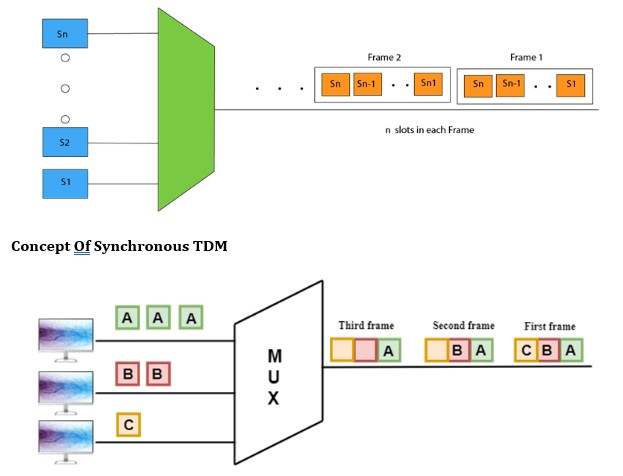
Concept Of Synchronous TDM
In the above figure, the Synchronous TDM technique is implemented. Each device is allocated with some time slot. The time slots are transmitted irrespective of whether the sender has data to send or not.
Disadvantages Of Synchronous TDM:
- The capacity of the channel is not fully utilized as the empty slots are also transmitted which is having no data. In the above figure, the first frame is completely filled, but in the last two frames, some slots are empty. Therefore, we can say that the capacity of the channel is not utilized efficiently.
- The speed of the transmission medium should be greater than the total speed of the input lines. An alternative approach to the Synchronous TDM is Asynchronous Time Division Multiplexing.
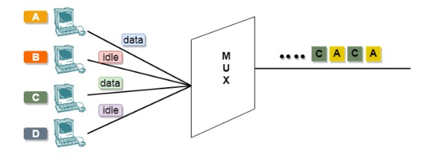
Asynchronous TDM
- An asynchronous TDM is also known as Statistical TDM.
- An asynchronous TDM is a technique in which time slots are not fixed as in the case of Synchronous TDM. Time slots are allocated to only those devices which have the data to send. Therefore, we can say that Asynchronous Time Division multiplexor transmits only the data from active workstations.
- An asynchronous TDM technique dynamically allocates the time slots to the devices.
- In Asynchronous TDM, total speed of the input lines can be greater than the capacity of the channel.
- Asynchronous Time Division multiplexor accepts the incoming data streams and creates a frame that contains only data with no empty slots.
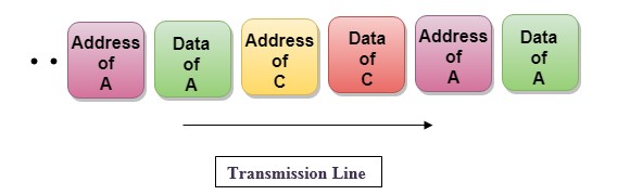
- In Asynchronous TDM, each slot contains an address part that identifies the source of the data.
- The difference between Asynchronous TDM and Synchronous TDM is that many slots in Synchronous TDM are unutilized, but in Asynchronous TDM, slots are fully utilized. This leads to the smaller transmission time and efficient utilization of the capacity of the channel.
- In Synchronous TDM, if there are n sending devices, then there are n time slots. In Asynchronous TDM, if there are n sending devices, then there are m time slots where m is less than n (m<n).
- The number of slots in a frame depends on the statistical analysis of the number of input lines.
Concept Of Asynchronous TDM
In the above diagram, there are 4 devices, but only two devices are sending the data, i.e., A and C. Therefore, the data of A and C are only transmitted through the transmission line.
Frame of above diagram can be represented as:
The above figure shows that the data part contains the address to determine the source of the data.
CONCENTRATOR
A type of multiplexor that combines multiple channels onto a single transmission medium in such a way that all the individual channels can be simultaneously active. For example, ISPs use concentrators to combine their dial-up modem connections onto faster T-1 lines that connect to the Internet.
Concentrators are also used in local-area networks (LANs) to combine transmissions from a cluster of nodes. In this case, the concentrator is often called a hub or MAU..
Data Transmission Modes.
Data Transmission mode defines the direction of the flow of information between two communication devices. It is also called Data Communication or Directional Mode. It specifies the direction of the flow of information from one place to another in a computer network. In the Open System Interconnection (OSI) Layer Model, the Physical Layer is dedicated to data transmission in the network. It mainly decides the direction of data in which the data needs to travel to reach the receiver system or node. The data transmission modes can be characterized in the following three types based on the direction of exchange of information:
- Simplex
- Half-Duplex
- Full Duplex
The data transmission modes can be characterized in the following two types based on the synchronization between the transmitter and the receiver:
- Synchronous
- Asynchronous
The data transmission modes can be characterized in the following two types based on the number of bits sent simultaneously in the network:
- Serial
- Parallel
According to the Direction of Exchange of Information:
1. Simplex
Simplex is the data transmission mode in which the data can flow only in one direction, i.e., the communication is unidirectional. In this mode, a sender can only send data but cannot receive it. Similarly, a receiver can only receive data but cannot send it.
Simplex mode
This transmission mode is not so popular because we cannot perform two-way communication between the sender and receiver in this mode. It is mainly used in the business field as in sales that do not require any corresponding reply. It is similar to a one-way street.
For Example, Radio and TV transmission, keyboard, mouse, etc.
Advantages a Simplex transmission mode:
- It utilizes the full capacity of the communication channel during data transmission.
- It has the least or no data traffic issues as data flows only in one direction.
- Simplex mode is the easiest and most reliable mode of communication.
- It is the most cost-effective mode, as it only requires one communication channel. There is no need for coordination between the transmitting and receiving devices, which simplifies the communication process.
- Simplex mode is particularly useful in situations where feedback or response is not required, such as broadcasting or surveillance.
Disadvantages of a Simplex transmission mode:
- It is unidirectional in nature having no inter-communication between devices.
- There is no way to verify if the transmitted data has been received correctly.
- Simplex mode is not suitable for applications that require bidirectional communication
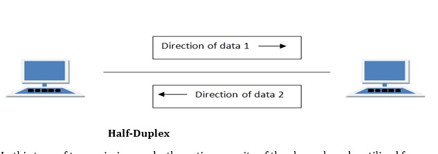
2. Half-Duplex
Half-Duplex is the data transmission mode in which the data can flow in both directions but in one direction at a time. It is also referred to as Semi-Duplex. In other words, each station can both transmit and receive the data but not at the same time. When one device is sending the other can only receive and vice-versa.
Half-Duplex
In this type of transmission mode, the entire capacity of the channel can be utilized for each direction. Transmission lines can carry data in both directions, but the data can be sent only in one direction at a time. This type of data transmission mode can be used in cases where there is no need for communication in both directions at the same time. It can be used for error detection when the sender does not send or the receiver does not receive the data properly. In such cases, the data needs to be transmitted again by the receiver.
For Example, Walkie-Talkie, Internet Browsers, etc.
Advantages of a half-duplex transmission mode:
- It facilitates the optimum use of the communication channel.
- It provides two-way communication.
Disadvantages of a half-duplex transmission mode:
- The two-way communication cannot be established simultaneously at the same time.
- Delay in transmission may occur as only one way communication can be possible at a time.
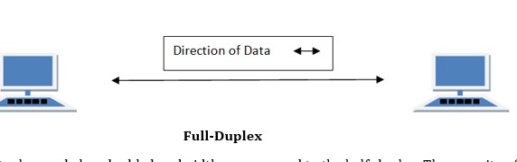
3. Full-Duplex
Full-Duplex is the data transmission mode in which the data can flow in both directions at the same time. It is bi-directional in nature. It is two-way communication in which both the stations can transmit and receive the data simultaneously.
Full-Duplex
Full-Duplex mode has double bandwidth as compared to the half-duplex. The capacity of the channel is divided between the two directions of communication. This mode is used when communication in both directions is required simultaneously.
For Example; A Telephone Network, in which both the persons can talk and listen to each other simultaneously.
Advantages of a full-duplex transmission mode:
- The two-way communication can be carried out simultaneously in both directions.
- It is the fastest mode of communication between devices.
Disadvantages of a half-duplex transmission mode:
- The capacity of the communication channel is divided into two parts. Also, no dedicated path exists for data transfer.
- It has improper channel bandwidth utilization as there exist two separate paths for two communicating devices.
According to the synchronization between the transmitter and the receiver:
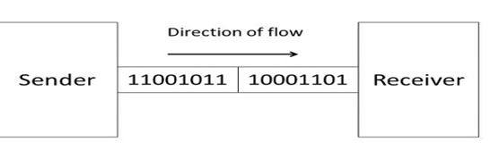
1. Synchronous Transmission
The Synchronous transmission mode is a mode of communication in which the bits are sent one after another without any start/stop bits or gaps between them. Actually, both the sender and receiver are paced by the same system clock. In this way, synchronization is achieved. In a Synchronous mode of data transmission, bytes are transmitted as blocks in a continuous stream of bits. Since there is no start and stop bits in the message block. It is the responsibility of the receiver to group the bits correctly. The receiver counts the bits as they arrive and groups them in eight bits unit. The receiver continuously receives the information at the same rate that the transmitter has sent it. It also listens to the messages even if no bits are transmitted.
Example:
- Chat Rooms
- Telephonic Conversations
- Video Conferencing
In synchronous mode, the bits are sent successively with no separation between each character, so it becomes necessary to insert some synchronization elements with the message, this is called ” Character-Level Synchronization “.For Example, if there are two bytes of data, say(10001101, 11001011) then it will be transmitted in the synchronous mode as follows:
Synchronous mode
For Example, communication in CPU, RAM, etc.
Advantages of a Synchronous transmission mode:
- Transmission speed is fast as there is no gap between the data bits.
Disadvantages of a Synchronous transmission mode:
- It is very expensive.
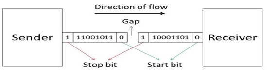
2. Asynchronous Transmission
The Asynchronous transmission mode is a mode of communication in which a start and the stop bit is introduced in the message during transmission. The start and stop bits ensure that the data is transmitted correctly from the sender to the receiver. Generally, the start bit is ‘0’ and the end bit is ‘1’. Asynchronous here means ‘asynchronous at the byte level’, but the bits are still synchronized. The time duration between each character is the same and synchronized.
Example:
- Forums
- Letters
In an asynchronous mode of communication, data bits can be sent at any point in time. The messages are sent at irregular intervals and only one data byte can be sent at a time. This type of transmission mode is best suited for short-distance data transfer.
For Example, if there are two bytes of data, say (10001101, 11001011) then it will be transmitted in the asynchronous mode as follows:
Asynchronous mode
For Example, Data input from a keyboard to the compute
Advantages of using an Asynchronous transmission mode:
- It is a cheap and effective mode of transmission.
- Data transmission accuracy is high due to the presence of start and stop bits.
Disadvantages of using an Asynchronous transmission mode:
- The data transmission can be slower due to the gaps present between different blocks of data.
According to the number of bits sent simultaneously in the network:
The difference between Synchronous Transmission and Asynchronous Transmission
| S. No. | Synchronous Transmission | Asynchronous Transmission |
| 1. | In Synchronous Transmission, data is sent in form of blocks or frames. | In Asynchronous Transmission, data is sent in form of bytes or characters. |
| 2. | Synchronous transmission is fast. | Asynchronous transmission is slow. |
| 3. | Synchronous transmission is costly. | Asynchronous transmission is economical. |
| 4. | In Synchronous transmission, the time interval of transmission is constant. | In Asynchronous transmission, the time interval of transmission is not constant, it is random. |
| 5. | In this transmission, users have to wait till the transmission is complete before getting a response back from the server. | Here, users do not have to wait for the completion of transmission in order to get a response from the server. |
| 6. | In Synchronous transmission, there is no gap present between data. | In Asynchronous transmission, there is a gap present between data. |
| 7. | Efficient use of transmission lines is done in synchronous transmission. | While in Asynchronous transmission, the transmission line remains empty during a gap in character transmission. |
| 8. | The start and stop bits are not used in transmitting data. | The start and stop bits are used in transmitting data that imposes extra overhead. |
| 9. | Synchronous transmission needs precisely synchronized clocks for the information of new bytes. | Asynchronous transmission does not need synchronized clocks as parity bit is used in this transmission for information of new bytes. |
| 10. | Errors are detected and corrected in real time. | Errors are detected and corrected when the data is received. |
| 11. | Low latency due to real-time communication. | High latency due to processing time and waiting for data to become available. |
| 12. | Examples: Telephonic conversations, Video conferencing, Online gaming. | Examples: Email, File transfer, Online forms. |
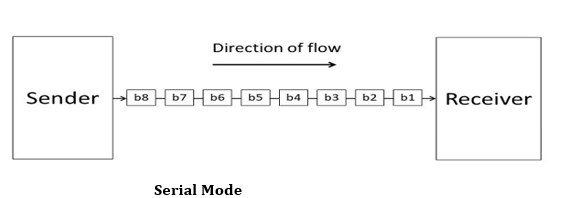
1. Serial
The Serial data transmission mode is a mode in which the data bits are sent serially one after the other at a time over the transmission channel.
Serial Mode
It needs a single transmission line for communication. The data bits are received in synchronization with one another. So, there is a challenge of synchronizing the transmitter and receiver.
In serial data transmission, the system takes several clock cycles to transmit the data stream. In this mode, the data integrity is maintained, as it transmits the data bits in a specific order, one after the other. This type of transmission mode is best suited for long-distance data transfer, or the amount of data being sent is relatively small.
For Example, Data transmission between two computers using serial ports.
Following are the advantages of using a serial transmission mode:
- It can be used for long-distance data transmission as it is reliable.
- The number of wires and complexity is less.
- It is cost-effective.
Following are the disadvantages of using a serial transmission mode:
- The Data transmission rate is slow due to a single transmission channel.
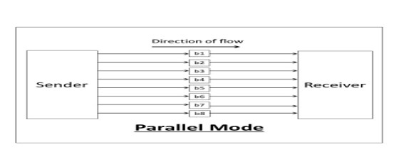
2. Parallel
The Parallel data transmission mode is a mode in which the data bits are sent parallelly at a time. In other words, there is a transmission of n-bits at the same time simultaneously.

Multiple transmission lines are used in such modes of transmission. So, multiple data bytes can be transmitted in a single system clock. This mode of transmission is used when a large amount of data has to be sent in a shorter duration of time. It is mostly used for short-distance communication. For n-bits, we need n-transmission lines. So, the complexity of the network increases but the transmission speed is high. If two or more transmission lines are too close to each other, then there may be a chance of interference in the data, degrading the signal quality.
For Example, Data transmission between computer and printer.
Advantages of using a parallel transmission mode:
- It is easy to program or implement.
- Data transmission speed is high due to the n-transmission channel.
Disadvantages of using a parallel transmission mode:
- It requires more transmission channels, and hence cost-ineffective.
- Interference in data bits, likewise in video conferencing.
Condition to be considered when selecting a data transmission mode:
- Transmission Rate.
- The Distance that it covers.
- Cost and Ease of Installation.
- The resistance of environmental conditions.
Communication could be simple, including only one sender and one receiver, or it could involve several senders and receivers. We can distinguish between Point-to-Point and Multi-Point communication based on the number of senders and receivers in a communication.
Point-to-Point Communication
In telecommunications, a point-to-point connection is a communications link between two communication endpoints or nodes. A telephone call is an example of this, in which two phones are linked, and what one caller says can only be heard by the other.
Point-Point communication.
A “point-to-multipoint” or broadcast link, on the other hand, allows multiple nodes to receive information sent by a single node. Leased lines and microwave radio relays are also examples of point-to-point connections.
In a point-to-point communication, there will be a transmitter and a receiver connected together with a suitable connection. The capacity of the connecting channel remains unchanged throughout the communication.
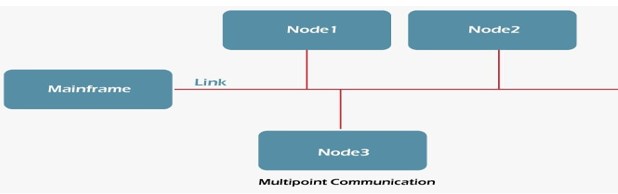
Multi-Point Communication
In telecommunications, point-to-multipoint communication (P2MP, PTMP, or PMP) is a form of one-to-many communication that allows numerous routes to be established from a single site to several locations.
Multipoint Communication
The usage of gigahertz radio frequencies for point-to-multipoint telecommunications is common in wireless Internet and IP telephony. P2MP systems have been created with and without a return channel from the numerous receivers. The system employs a kind of time-division multiplexing to enable the return channel traffic, which is transmitted from a central antenna to numerous receiving antennas.
Difference between Point-to-Point and Multi-point Communication
The following table highlights the important differences between Point-to-Point and Multi-point Communication.
| Key | Point-to-Point Communication | Multi-point Communication |
| Definition | Point-to-point communication is a method in which the channel of communication is shared only between two devices or nodes. | Multi-point communication is a form of communication in which the channel is shared among multiple devices or nodes. |
| Load sharing | In case of Point-to-point communication, the channel is shared only between two nodes, so the load and capacity of the channel is available only to two nodes. | In case of Multi-point communication, the channel capacity is divided among multiple participant nodes. |
| Parties involved | In case of Point-to-point communication only two parties get involved, one as the Sender and the other as the Receiver. | In case of Multi-point communication, there could be multiple parties, however the role of parties could either be sender or receiver and some parties may behave like both. |
| Reliability | Point-to-point communication involves only two parties and the chances for information modulation is very less, hence this type of communication is more reliable as compared to Multi-point communication. | Due to the involvement of multiple parties, the chances for information modulation is more and hence Multi-point communication is comparatively less reliable as compared to Point-to-Point communication. |
| Error Prone | Point-to-point communication is more error prone as compared to Multi-point communication. | Multi-point communication is less error prone as compared to Point-to-Point communication. |
| Security and Privacy | Point-to-point communication is more secure and private as compared to Multi-point communication. | Multi-point communication is less secure and private as compared to Point-to-point communication. |
| Examples | Frame Relay, T-carrier, X.25 | Frame Relay, Token Ring, Ethernet, ATM |
Communications Software
As this category loosely lumps together different apps, we can categorize them based on how they are usually packaged. In contrast, others are integrated with a bigger system like CRM software platforms or project management tools.
- Unified communications system. This features the works–phone support, ticketing, intranet, VoIP, and other enterprise tools like reporting and analytics. Example: RingCentral
- Web conferencing. It is ideal for organizations with remote teams, global clients, or a long web mailing list.
Example: GoToMeeting - Live chat. Many vendors offer live chat as a standalone app that you can embed in your digital channels like website, social media page, newsletter, and custom app. Live chat apps today are sophisticated, able to offer marketing software features like lead qualification and nurturing, provide analytics on web visits and FAQs, or integrate with your CRM or other key business systems for shared data.
Example: LiveAgent
Benefits of Communications Software
- Work remotely. Teams are increasingly distributed not just within the country but globally. Businesses today need communication tools to keep everyone on the same page in real-time to conduct daily operations, work collaboratively, or address urgent situations.
- Boost productivity. Communicate with clarity with teams and avoid costly errors like missed deadlines, wrong outputs, and mismatched expectations.
- Easy to integrate. Most live chat, email and other messaging apps are so ubiquitous that they work smoothly with bigger systems like CRM software, project management systems, help desk software tools, ecommerce platforms, and other SaaS solutions.
- Capture important information. One of the major advantages of communications software is it acts as a repository of data. Many apps can record or archive message exchanges and audio and video calls, meaning you can capture important details such as customer queries, discussion points, and meeting minutes. The benefits from this are plenty, including sorting promising customer inquiries for leads, referencing discussion points as proof of agreement, and preparing minutes.
- Minimize costs. Many of the best communications software solutions can be accessed using your employees’ smartphone or tablet.
Operating System
An operating system is a collection of programs that controls the running of programs and organizes the resources of a computer system. These resources are the hardware components of the system, such as keyboards, printers, monitors, and disk drives. An application program relies on the operating system to perform many detailed tasks associated with the internal workings of the computer. The operating system also accepts commands directly from you to manage files and security. There are many extensions to the AIX operating system that allow you to customize your environment.
Root-User Processes
Root-user processes are programs that can be run only by a user with root authority. A system administrator has root authority for all processes.
- Read or write any object
- Call any system function
EDI, which stands for Electronic Data Exchange, is the secure, automated exchange of electronic documents between trading partners using a standardized format that enables computer systems to communicate with each other.
With everything you need to implement EDI, documents flow directly in and out of your accounting or ERP system with little or no human intervention. This accelerates order processing, the pick/pack/ship process, invoicing and other essential supply chain functions.
The main benefit of integrated EDI is that it removes the need to manually retype data which eliminates costly data entry errors. This saves considerable time and money and improves your customers’ experience. An integrated EDI solution not only increases efficiency through automation, it also saves you money on postage, paper, physical document storage and the time it takes to rekey data and handle paper documents.
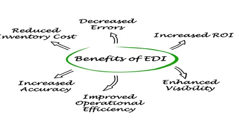
The advantages and benefits of Electronic Data Interchange
- Improved operational efficiency: Automating the flow of messages with integrated EDI improves the speed and efficiency of your operations by eliminating the need to manually rekey data in multiple systems.
- Fewer errors: By removing manual, paper-based processes the occurrence of human errors is dramatically reduced or even eliminated.
- Increased accuracy: Automated message validation ensures that errors are flagged and rectified before they impact your trading partners and data integrity in your internal systems is maintained.
- Increased return on investment (ROI): Automation through integrated EDI enables you to maximize the benefits of EDI and move beyond simply complying with your customers’ EDI requirements.
- Enhanced visibility: EDI provides full transparency of the ordering and invoicing process for you and your trading partners. This end-to-end visibility enables more informed decisions to be made and ultimately improves the service delivered to consumers.
Reduced inventory cost: Increased visibility within the supply chain eliminates unknowns and can therefore enable you to reduce the levels of inventory you need to hold.
Types of EDI
There are several different types of EDI, each with its own specific format and use case. Here are some of the most common types of EDI:
1. Direct EDI (Point-to-Point):
Direct EDI, also known as point-to-point EDI, is a type of EDI where businesses exchange electronic documents directly with their trading partners without using an intermediary. This method is useful for businesses that have a limited number of trading partners and want to have complete control over their EDI transactions.
2. EDI via a Network Services Provider (EDI VAN):
EDI via VAN (Value Added Network) is a type of EDI where businesses exchange electronic documents through a third-party provider that offers EDI network services. VANs provide a secure and reliable way for businesses to exchange EDI documents with their trading partners. VANs offer additional features such as message tracking and reporting, data translation, and data mapping.
3. AS2 EDI:
EDI via AS2 (Applicability Statement 2) is a type of EDI that uses the AS2 internet communications protocol to exchange documents. AS2 provides a secure and reliable way to exchange EDI documents over the internet by using digital certificates and encryption.
4. Web EDI:
Web EDI is a type of EDI that uses a web-based portal to exchange electronic documents between businesses. Web EDI is an easy-to-use method for businesses that do not have the technical expertise or resources to implement a traditional EDI system. Web EDI allows businesses to exchange documents such as purchase orders and invoices with their trading partners using a web browser.
5. Mobile EDI:
Mobile EDI is a type of EDI that allows businesses to exchange electronic documents using mobile devices such as smartphones and tablets. This method is useful for businesses that need to exchange EDI documents while on the go. Mobile EDI apps are available for both iOS and Android devices, allowing businesses to send and receive EDI documents from anywhere.
6. EDI Outsourcing:
EDI outsourcing is a type of EDI where businesses outsource their EDI operations to a third-party provider. The provider handles all aspects of the EDI process, including data mapping, translation, and communication with trading partners. This method is useful for businesses that do not have the technical expertise or resources to implement and manage an in-house EDI system.
7. EDI Software:
EDI software is a type of EDI that businesses use to implement an in-house EDI system. The software provides all the tools necessary to exchange electronic documents with trading partners, including data mapping, translation, and communication protocols. This method is useful for businesses that have the technical expertise and resources to implement and manage their own EDI system. Learn more about our robust EDI software that automates every EDI transaction.
Top VoIP Phone Features
In addition to some serious cost savings, extensive phone features are another important motivation why so many companies switch to VoIP.
Here are the top features offered in a VoIP phone system:
- Unlimited Calling – Call any phone in the United States and Canada as much as you want. No minutes to track. Instant savings.
- Online Faxing – Send and receive unlimited faxes, just like email. No hardware or wires. Faxing is finally easy and straightforward.
- Auto Attendant – Greet callers instantly when they call and direct them to the right person. Give your company an excellent first impression from the moment they call.
- Call Queues – Handle calls when your team is busy. Callers wait in line for the next agent. You and your customers will love it.
- HD Voice Quality – Get superior sounding phone calls. The g.722 codec is engineered to eliminate annoying static for vibrant conversations.
- Conference Lines – Use a dedicated conference line for meetings with up to nine participants. Meet, moderate, and record in HD.
- Voicemail-to-Email – Get voicemail messages delivered to your inbox. Listen to voicemails and respond through your email.
- Smartphone App – Answer business calls from on the go. Never miss an important call again. It’s available free for iOS and Android devices.
- Real-Time Presence – See who’s available to receive calls and chat messages. Live status updates are accurate and straightforward.
- Team Collaboration – Chat with your team on one system. Flawless video and screen sharing enables you to get work done faster.
- Text Messaging (SMS) – Send and receive text messages with customers. Perfect for quick updates and appointment reminders.
- CRM Integrations – Optional integration you can use with your current CRM. Boost productivity with a deeply integrated workflow.
These are just the tip of the iceberg when it comes to our VoIP features. If your company has a contact center, you should focus on these call center features to achieve faster ROI.
VoIP Phone System Requirements
Thinking about setting up a VoIP phone system in your business? How can you make sure your business is ready?
Network Bandwidth
You’ll need a reliable internet connection such as DSL, cable, or fiber from an Internet Service Provider (ISP). The standard bandwidth required for VoIP is 100 Kbps per device. Depending on the type of data and features you’ll use, you might need more bandwidth than the standard.
Check your connection quality with our free VoIP speed test.
Phones & Devices
Another major factor is ensuring that you have the right devices in place.
You must have a SIP phone, a softphone, or an Analog Telephone Adapter to complete calls over VoIP. Here’s a quick summary of each:
- SIP Phones – All VoIP phones are SIP phones and vice-versa. They establish calls by using a VoIP service provider. Nextiva offers a wide variety of VoIP desk phones that offer a ton of functionality for both small businesses and enterprises.
- Softphones – If you don’t need a traditional telephone, you can just download an app to make VoIP calls using your cellphone, laptop, or desktop. These VoIP applications keep your Caller ID separate because the voice data is handled directly through your VoIP provider.
Analog Telephone Adapters – For the holdouts of analog phones, never fear. With an ATA, you can retrofit your phones, so they function correctly over VoIP. They might not have all the conferencing capabilities available, but they
Teleconferencing
Teleconferencing means meeting through a telecommunication medium. It is a generic term for linking people between two or more locations by electronics. There are at least six types of teleconferencing: audio, audio graphic, computer, video, business television (BTV), and distance education. The methods used differ in the technology, but common factors contribute to the shared definition of teleconferencing:
Types of Teleconferences
1.Audio Teleconference
Voice-only; sometimes called conference calling. Interactively links people in remote locations via telephone lines. Audio bridges tie all lines together. Meetings can be conducted via audio conference. Preplanning is necessary which includes naming a chair, setting an agenda, and providing printed materials to participants ahead of time so that they can be reviewed. Distance learning can be conducted by audio conference. In fact, it is one of the most underutilized, yet cost effective methods available to education. Instructors should receive training on how to best utilize audio conferences to augment other forms of distance learning.
2.Audio graphics Teleconference
Uses narrow-band telecommunications channels to transmit visual information such as graphics, alpha-numeric, documents, and video pictures as an adjunct to voice communication. Other terms are desk-top computer conferencing and enhanced audio. Devices include electronic tablets/boards, freeze-frame video terminals, integrated graphics systems (as part of personal computers), Fax, remote-access microfiche and slide projectors, optical graphic scanners, and voice/data terminals.
Audio graphics can be used for meetings and distance learning.
3. Computer Teleconference
Computer conferencing is an emerging area for distance education. Some institutions offer credit programs completely by computer. Students receive texts and workbooks via mail. Through common files assigned to a class which each student can assess, teachers upload syllabi, lectures, grades and remarks. Students download these files, compose their assignment and remarks off-line, and then upload them to the common files.
4.Video Teleconference
Video conferencing is an effective way to use one teacher who teaches to a number of sites. It is very cost effective for classes which may have a small number of students enrolled at each site. In many cases, video conferencing enables the institution or a group of institutions to provide courses which would be cancelled due to low enrolment or which could not be supported otherwise because of the cost of providing an instructor in an unusual subject area. Rural areas benefit particularly from classes provided through video conferencing when they work with a larger metropolitan institution that has full-time faculty.
Through teleconferencing, institutions are able to serve all students equitably.
- Use a telecommunications channel
- Link people at multiple locations
- Interactive to provide two-way communications
- Dynamic to require users’ active participation
Advantages of using teleconferencing
1. Move Information – Not People: Electronic delivery is more efficient than physically moving people to a site, whether it is a faculty member or administrator.
2. Save Time: Content presented by one or many sources is received in many places simultaneously and instantly. Travel is reduced resulting in more productive time. Communication is improved and meetings are more efficient. It adds a competitive edge that face-to-face meetings do not.
3. Lower Costs :Costs (travel, meals, lodging) are reduced by keeping employees in the office, speeding up product development cycles, improving performance through frequent meetings with timely information.
4. Accessible: Through any origination site in the world. Larger Audiences: More people can attend. The larger the audience, the lower the cost per person.
5. Larger Audiences: More people can attend. The larger the audience, the lower cost per person.
6. Adaptable: Useful for business, associations, hospitals, and institutions to discuss, inform, train, educate or present.
7. Flexible :With a remote receive or transmit truck, a transmit or receive site can be located anywhere.
8. .Security: Signals can be encrypted (scrambled) when it is necessary. Encryption prevents outside viewers.
9. .Unity :Provides a shared sense of identity. People feel more a part of the group…more often. Individuals or groups at multiple locations can be linked frequently.
10. .Timely :For time-critical information, sites can be linked quickly. An audio or point-to-point teleconference can be convened in three minutes.
11. .Interactive : Dynamic; requires the user’s active participation. It enhances personal communication. When used well for learning, the interactivity will enhance the learning and the teaching experience.
Disadvantages of using teleconferencing
- staffing necessary learning
- time to adapt to technology may be expensive
- diminishes personal touch hearing issues
- No Visual Presentation Interruptions
- Lack of Eye contact
- Lack of body Language.
IT system behind teleconferencing
- Personal computer
- Telephone lines or satellite hook-up
- Monitor
- Microphone
- Webcam
- Speakers
Effect of Teleconferencing on Business
- Let all branches know what is going on
- Easy communication over long distance
- Saves time, money, and energy
- Reduces face to face
What is a Network.
A network is a group of two or more computers or other electronic devices that are interconnected for the purpose of exchanging data and sharing resources.
In information technology, a network is defined as the connection of at least two computer systems, either by a cable or a wireless connection. The simplest network is a combination of two computers connected by a cable. This type of network is called a peer-to-peer network. There is no hierarchy in this network; both participants have equal privileges. Each computer has access to the data of the other device and can share resources such as disk space, applications or peripheral devices (printers, etc.).
Today’s networks tend to be a bit more complex and don’t just consist of two computers. Systems with more than ten participants usually use client-server networks. In these networks, a central computer (server) provides resources to the other participants in the network (clients).
The main advantages of networks are:
- Shared use of data
- Shared use of resources
- Central control of programs and data
- Central storage and backup of data
- Shared processing power and storage capacity
- Easy management of authorizations and responsibilities
How does a network work?
In a typical client-server network there is a central node called the server. The server is connected to the other devices, which are called clients. This connection is either wireless (Wireless LAN) or wired (LAN).
In a typical home network, the router assumes the role of the server. It is connected to the Internet and provides the “Internet” resource for the other devices (computers, smartphones, etc.).
Client-server architecture
In larger networks, such as corporate networks, the server is usually a central computer. This computer is used exclusively for running special server software and services, not regular applications and programs. The server must operate continuously, whereas the other computers (clients) can be switched off.
The server and the client communicate as follows in this server-based network: The client first sends a request to the server. The server evaluates the request and then transmits the response. In this model, the client always connects to the server, never the other way around.
Network protocols
Network protocols ensure smooth communication between the different components in a network. They control data exchange and determine how communication is established and terminated as well as which data is transmitted. There are usually multiple network protocols that each perform a specific subtask and are hierarchically organized into layers.
Network addresses
In addition, it is necessary to ensure that the transmitter and receiver can be correctly identified. Network addresses are used for this purpose. In computer networks, each computer typically has an IP address, similar to a telephone number, that uniquely identifies the computer. This internal IP address is used only for communication between the participants in the local network. For communication on the Internet, external IP addresses are used that are automatically assigned by the Internet provider.
A distinction is also made between IPv4 and IPv6 addresses. IPv4 addresses used to be standard, but only a total of around 4.3 billion of these addresses could be assigned before they were exhausted. Due to the massive expansion of the Internet, additional IP addresses were urgently needed. Therefore, the new IPv6 standard was developed, allowing up to 3.4 x 1038 (340 sextillion) addresses. This should be sufficient for the future.
Types of networks
Networks are usually divided into different network types according to transmission type and range, that is, depending on how or how far the data is transmitted.
Wireless vs. Wired
Networks are classified by transmission type as either wireless or wired. Examples of wireless networks include Wi-Fi networks based on the IEEE 802.11 standard, or the LTE networks used for mobile devices and smartphones. Wired networks such as DSL are also known as broadband Internet.
Network range
Networks are typically classified by range as follows:
- Personal Area Network (PAN): A PAN is used for interconnecting devices within a short range of approximately 10 meters. Examples include Bluetooth technology or Apple’s Airdrop ad hoc Wi-Fi service.
- Local Area Network (LAN): Local area networks are among the most widespread networks and are used in households or small and medium-sized companies.
- Metropolitan Area Network (MAN): These types of networks cover cities or single geographic regions.
- Wide Area Network (WAN): The nationwide broadband or cellular network in the US is an example of a Wide Area Network.
- GAN (Global Area Network): The best known example of a global network is the Internet.
Note that there is some overlap between the different network types: As a Wi-Fi user, you are simultaneously part of a WAN and a GAN when you’re connected to the Internet.
Network controllers
A network controller is a software that orchestrates network functions. It serves as an intermediary between the business and the network infrastructure. The organization enters their desired business objectives into the controller which in turn sets up the network to deliver on those objectives. Network controllers do their jobs by:
- Maintaining an inventory of devices in the network and their status
- Automating device operations such as configurations and image updates
- Analyzing network operations, identifying potential issues, and suggesting remediations
- Providing a platform for integration with other applications such as reporting systems
Use of network controllers
The network is the lifeblood of a modern organization. The network not only provides basic connectivity but also security, enhanced collaboration, quality and continuity of service, etc. The architecture, infrastructure, and management of the network are therefore vital and increasingly tied to the success of the business.
A network controller manages and orchestrates all aspects of a network making sure that it is operating flawlessly and delivering on business objectives.
How network controllers solve today’s IT challenges
- Reduce operating costs: One of the biggest issues before IT today is the increasing cost of operations. These costs are a result of providing services to increasing number of users and devices who connect to the network from offices, homes, coffee shops, airports, etc., and applications that are distributed in private data centers and public clouds. This growth is outpacing IT capabilities and manual management efforts. Network Controllers automate operations that result in better scaling, reducing time, eliminating errors, and cutting costs.
- Increase availability: A network controller collects and analyzes network traffic to proactively detect any potential issues before they become real problems. It can perform root-cause analysis and alert IT operations who can take corrective and preventive steps to ensure network services always remain available.
- Improve agility: A network controller makes networks agile and responsive to business needs. It implements required changes on all network devices consistently and universally without the time-consuming need for device-by-device configurations.
- Enhance security: A network controller’s thorough analysis of network traffic may reveal potential security threats. The controller can then act to isolate the threat and prevent its spread.
- Accelerate adoption of intent-based networking: Organizations are taking steps to make their networks agile and responsive, to keep pace with evolving business needs. They’re rearchitecting their networks to align with intent-based networking (IBN) principles. A network controller plays a foundational role in the evolution of legacy networks to IBN.
Computer Network.
A computer network is a collection of computers capable of transmitting, receiving, and exchanging voice, data, and video traffic. Because of the capability of computer networking, everything is becoming more automated and capable of communicating and managing itself. Because of the internet’s powerful network, you can use Google and YouTube and watch other information with just a few clicks. It is possible due to computer networks.
Timeline of Computer Networks
- In 1957, Advanced Research Project Agency was formed by the US.
- In 1961, the idea of ARPANET was proposed by Leonard Kleinrock.
- In 1965, the term packet was used by Donald Davies.
- In 1969, ARPANET became functional, and the internet was officially born, with the first data transmission sent between UCLA and SRI on October 29, 1969, at 10:30 p.m.
- In 1971, Ray Tomlinson sent the first email, and the foundation for Wi-Fi was laid with the use of ALOHAnet.
- In 1973, Robert Metcalfe developed Ethernet at Xerox PARC, and the first experimental VoIP call was made.
- In 1976, the first true IP router was developed by Ginny Strazisar.
- In 1978, Bob Kahn invented the TCP/IP protocol for networks developed.
- In 1981, Internet Protocol version 4, or IPv4, was officially defined in RFC 791 in 1981.
- In 1983, DNS was introduced by Paul Mockapetris.
- In 1988, details about network firewall technology were first published 1988.
- In 1996, IPv6 was introduced.
- In 1997, the first version of the 802.11 standards for Wi-Fi was introduced in June 1997, providing transmission speeds up to 2 Mbps.
- In 2002-2004, Web 2.0 was introduced.
Modern Computer Networks
From the first computer network, Arpanet, to the latest Web 3.0, the computer network has evolved in speed, reliability, and user experience. In today’s world, everything is Speed, and to increase the network’s Speed. We are currently replacing copper coaxial cableswithoptical fiber cables. Some things that make the network better and better with time are described as follows.
Optical Fiber Cables
An optical fiber is a thin strand of pure glass that works as a long-distance waveguide for light. It works on the principle of total internal reflection. The core, which carries the actual light signal, and the cladding, a sheet of glass around the core, are the two layers of glass that make up the device. The refractive index of the cladding is lower than that of the core, and this results in TIR within the core. Two significant service providers that provide optical fiber-based internet are Reliance JIO and Indian Airtel Xstream Fiber. Both service providers claim to provide a speed of 1 GBPS, which is enormous.
LI-FI Technology
Li-Fi is light-based bi-directional, fully networked, wireless communication technology where the light source is used to transmit the data wirelessly. This is achieved by turning LED ON and OFF very rapidly(Million times per second), so that the flicker is not observable by the human eye. In this way, the data is transferred between the two devices wirelessly. Features provided by the Li-Fi are:
- Speed: Li-Fi can provide speeds up to 100 Gbps.
- Security: Light can not cross the walls, so data cannot be hacked by outsiders, providing one more layer of security.
- Safety: Unlike radio waves, light exposure is safer for humans.
- Congestion-free: The bandwidth of the light spectrum is 1000 times more than the radio spectrum; hence, it is congestion-free and free of electromagnetic interference.
- Efficiency: It uses LED for transmission, which minimizes the overall energy consumption.
Blockchain Technology
A blockchain is a database that holds encrypted data blocks and links them together to build a chronological single-source of truth for the information. Blockchains are well known for their critical function in keeping a secure and decentralized record of transactions in cryptocurrency systems like Bitcoin..
Web 3.0
The third generation of web technologies is known as Web 3.0 (Web3). Web 3.0 is still evolving and being defined, and as such, there isn’t a canonical, universally accepted definition. But one thing is certain: Web 3.0 will significantly emphasize decentralized applications and make considerable use of blockchain-based technologies. Machine Learning and Artificial Intelligence (AI) will be used in Web 3.0 to help empower more intelligent and adaptive applications.
Firewall
A firewall is a network security hardware or software application that monitors and filters incoming and outgoing network traffic according to a set of security rules. It serves as a firewall between internal private networks and public networks (such as the public internet). To route web traffic, firewalls generate ‘choke points,’ which are then examined against predefined parameters and acted upon accordingly. Some firewalls also keep track of traffic and connections in audit logs to see what is allowed and prohibited.
Network Topology
Topology defines the structure of the network of how all the components are interconnected to each other. There are two types of topology: physical and logical topology.
Types of Network Topology
Physical topology is the geometric representation of all the nodes in a network. There are six types of network topology which are Bus Topology, Ring Topology, Tree Topology, Star Topology, Mesh Topology, and Hybrid Topology.
1) Bus Topology
- The bus topology is designed in such a way that all the stations are connected through a single cable known as a backbone cable.
- Each node is either connected to the backbone cable by drop cable or directly connected to the backbone cable.
- When a node wants to send a message over the network, it puts a message over the network. All the stations available in the network will receive the message whether it has been addressed or not.
- The bus topology is mainly used in 802.3 (ethernet) and 802.4 standard networks.
- The configuration of a bus topology is quite simpler as compared to other topologies.
- The backbone cable is considered as a “single lane” through which the message is broadcast to all the stations.
- The most common access method of the bus topologies is CSMA (Carrier Sense Multiple Access).
Advantages of Bus topology:
- Low-cost cable: In bus topology, nodes are directly connected to the cable without passing through a hub. Therefore, the initial cost of installation is low.
- Moderate data speeds: Coaxial or twisted pair cables are mainly used in bus-based networks that support upto 10 Mbps.
- Familiar technology: Bus topology is a familiar technology as the installation and troubleshooting techniques are well known, and hardware components are easily available.
- Limited failure: A failure in one node will not have any effect on other nodes.
Disadvantages of Bus topology:
- Extensive cabling: A bus topology is quite simpler, but still it requires a lot of cabling.
- Difficult troubleshooting: It requires specialized test equipment to determine the cable faults. If any fault occurs in the cable, then it would disrupt the communication for all the nodes.
- Signal interference: If two nodes send the messages simultaneously, then the signals of both the nodes collide with each other.
- Reconfiguration difficult: Adding new devices to the network would slow down the network.
- Attenuation: Attenuation is a loss of signal leads to communication issues. Repeaters are used to regenerate the signal.
2) Ring Topology
- Ring topology is like a bus topology, but with connected ends.
- The node that receives the message from the previous computer will retransmit to the next node.
- The data flows in one direction, i.e., it is unidirectional.
- The data flows in a single loop continuously known as an endless loop.
- It has no terminated ends, i.e., each node is connected to other node and having no termination point.
- The data in a ring topology flow in a clockwise direction.
- The most common access method of the ring topology is token passing.
- Token passing: It is a network access method in which token is passed from one node to another node.
- Token: It is a frame that circulates around the network.
Working of Token passing
- A token moves around the network, and it is passed from computer to computer until it reaches the destination.
- The sender modifies the token by putting the address along with the data.
- The data is passed from one device to another device until the destination address matches. Once the token received by the destination device, then it sends the acknowledgment to the sender.
- In a ring topology, a token is used as a carrier.
Advantages of Ring topology:
- Network Management: Faulty devices can be removed from the network without bringing the network down.
- Product availability: Many hardware and software tools for network operation and monitoring are available.
- Cost: Twisted pair cabling is inexpensive and easily available. Therefore, the installation cost is very low.
- Reliable: It is a more reliable network because the communication system is not dependent on the single host computer.
Disadvantages of Ring topology:
- Difficult troubleshooting: It requires specialized test equipment to determine the cable faults. If any fault occurs in the cable, then it would disrupt the communication for all the nodes.
- Failure: The breakdown in one station leads to the failure of the overall network.
- Reconfiguration difficult: Adding new devices to the network would slow down the network.
- Delay: Communication delay is directly proportional to the number of nodes. Adding new devices increases the communication delay.
3) Star Topology
- Star topology is an arrangement of the network in which every node is connected to the central hub, switch or a central computer.
- The central computer is known as a server, and the peripheral devices attached to the server are known as clients.
- Coaxial cable or RJ-45 cables are used to connect the computers.
- Hubs or Switches are mainly used as connection devices in a physical star topology.
- Star topology is the most popular topology in network implementation.
Advantages of Star topology
- Efficient troubleshooting: Troubleshooting is quite efficient in a star topology as compared to bus topology. In a bus topology, the manager has to inspect the kilometers of cable. In a star topology, all the stations are connected to the centralized network. Therefore, the network administrator has to go to the single station to troubleshoot the problem.
- Network control: Complex network control features can be easily implemented in the star topology. Any changes made in the star topology are automatically accommodated.
- Limited failure: As each station is connected to the central hub with its own cable, therefore failure in one cable will not affect the entire network.
- Familiar technology: Star topology is a familiar technology as its tools are cost-effective.
- Easily expandable: It is easily expandable as new stations can be added to the open ports on the hub.
- Cost effective: Star topology networks are cost-effective as it uses inexpensive coaxial cable.
- High data speeds: It supports a bandwidth of approx 100Mbps. Ethernet 100BaseT is one of the most popular Star topology networks.
Disadvantages of Star topology
- A Central point of failure: If the central hub or switch goes down, then all the connected nodes will not be able to communicate with each other.
- Cable: Sometimes cable routing becomes difficult when a significant amount of routing is required.
4) Tree topology
- Tree topology combines the characteristics of bus topology and star topology.
- A tree topology is a type of structure in which all the computers are connected with each other in hierarchical fashion.
- The top-most node in tree topology is known as a root node, and all other nodes are the descendants of the root node.
- There is only one path exists between two nodes for the data transmission. Thus, it forms a parent-child hierarchy.
Advantages of Tree topology
- Support for broadband transmission: Tree topology is mainly used to provide broadband transmission, i.e., signals are sent over long distances without being attenuated.
- Easily expandable: We can add the new device to the existing network. Therefore, we can say that tree topology is easily expandable.
- Easily manageable: In tree topology, the whole network is divided into segments known as star networks which can be easily managed and maintained.
- Error detection: Error detection and error correction are very easy in a tree topology.
- Limited failure: The breakdown in one station does not affect the entire network.
- Point-to-point wiring: It has point-to-point wiring for individual segments.
Disadvantages of Tree topology
- Difficult troubleshooting: If any fault occurs in the node, then it becomes difficult to troubleshoot the problem.
- High cost: Devices required for broadband transmission are very costly.
- Failure: A tree topology mainly relies on main bus cable and failure in main bus cable will damage the overall network.
- Reconfiguration difficult: If new devices are added, then it becomes difficult to reconfigure.
5) Mesh topology
- Mesh technology is an arrangement of the network in which computers are interconnected with each other through various redundant connections.
- There are multiple paths from one computer to another computer.
- It does not contain the switch, hub or any central computer which acts as a central point of communication.
- The Internet is an example of the mesh topology.
- Mesh topology is mainly used for WAN implementations where communication failures are a critical concern.
- Mesh topology is mainly used for wireless networks.
- Mesh topology can be formed by using the formula:
Number of cables = (n*(n-1))/2;
Where n is the number of nodes that represents the network.
Mesh topology is divided into two categories:
- Full Mesh Topology: In a full mesh topology, each computer is connected to all the computers available in the network.
- Partial Mesh Topology: In a partial mesh topology, not all but certain computers are connected to those computers with which they communicate frequently.
Advantages of Mesh topology:
Reliable: The mesh topology networks are very reliable as if any link breakdown will not affect the communication between connected computers.
Fast Communication: Communication is very fast between the nodes.
Easier Reconfiguration: Adding new devices would not disrupt the communication between other devices.
Disadvantages of Mesh topology
- Cost: A mesh topology contains a large number of connected devices such as a router and more transmission media than other topologies.
- Management: Mesh topology networks are very large and very difficult to maintain and manage. If the network is not monitored carefully, then the communication link failure goes undetected.
- Efficiency: In this topology, redundant connections are high that reduces the efficiency of the network.
6) Hybrid Topology
- The combination of various different topologies is known as Hybrid topology.
- A Hybrid topology is a connection between different links and nodes to transfer the data.
- When two or more different topologies are combined together is termed as Hybrid topology and if similar topologies are connected with each other will not result in Hybrid topology. For example, if there exist a ring topology in one branch of ICICI bank and bus topology in another branch of ICICI bank, connecting these two topologies will result in Hybrid topology.
Advantages of Hybrid Topology
- Reliable: If a fault occurs in any part of the network will not affect the functioning of the rest of the network.
- Scalable: Size of the network can be easily expanded by adding new devices without affecting the functionality of the existing network.
- Flexible: This topology is very flexible as it can be designed according to the requirements of the organization.
- Effective: Hybrid topology is very effective as it can be designed in such a way that the strength of the network is maximized and weakness of the network is minimized.
Disadvantages of Hybrid topology
- Complex design: The major drawback of the Hybrid topology is the design of the Hybrid network. It is very difficult to design the architecture of the Hybrid network.
- Costly Hub: The Hubs used in the Hybrid topology are very expensive as these hubs are different from usual Hubs used in other topologies.
- Costly infrastructure: The infrastructure cost is very high as a hybrid network requires a lot of cabling, network devices, etc.
- The combination of various different topologies is known as Hybrid topology.
- A Hybrid topology is a connection between different links and nodes to transfer the data.
- When two or more different topologies are combined together is termed as Hybrid topology and if similar topologies are connected with each other will not result in Hybrid topology. For example, if there exist a ring topology in one branch of ICICI bank and bus topology in another branch of ICICI bank, connecting these two topologies will result in Hybrid topology.
CLIENT/SERVER NETWORK.
Like network topology differs, the design of the network also varies. They are either client/server or peer-to-peer networks. Client/server networks have central servers for everything while Peer-to-peer have devices to support the same functions. There are fours most important types of network –
1. Local Area Network
LAN is a local network connecting computers and devices in a very small geographical area like home, school, small offices, etc. Very commonly used for sharing resources like files, games, and other applications. It allows one type of transmission by connecting one computer to another. The number of computers cannot exceed 5000 in this case.
Characteristics of LAN
- Allows full control by the owner as it is a private network.
- It is comparatively fast in speed due to the smaller area.
- Works well for token rings and ethernet.
Advantages of LAN
- Many computer resources can share local area networks reducing hardware purchase costs.
- The licensed software can also work on multiple devices reducing the cost again.
- One hard disk can store the data of all of the computers in the network.
- Transfer of data and information is instant and easier between networked computers.
- Data is secure as it is in one place only.
- One internet connection works for all the networked computers.
Disadvantages of LAN
- The installation charges of the setting cost quite high.
- The admin has access to all the files reducing the privacy of the user.
- An unauthorized person can access all the data in one go.
- It needs daily administration as there are many setup-related issues.
2. Personal Area Network (PAN)
This kind of network connects computers for solely personal use with 10m of range. The man behind its development is Thomas Zimmerman. Personal devices like laptops, mobile phones, and play stations usually use this network.
Characteristics of PAN
- They are of two types – wired personal area network and wireless personal area network.
- Wireless networks use WiFi, Bluetooth but have a very low range.
- The wired network uses USB.
- Body area networks move with the person like a mobile network.
- An offline network is a home network for connecting printers, tv, etc.
- Small home offices use VPN-based corporate networks.
Advantages of PAN
- They are most secure and safe
- Has a short-range solution becoming faster
- Strictly restricted to limited space
Disadvantages of PAN
- Many device connections may lead to bad or poor speed.
- The distance limits the user space of the network
3. Metropolitan Area Network (MAN)
It has a computer connection across a larger space like a city, university campus, etc. Unlike LAN it moves beyond a building or site. It can cover approximately several miles of area.
Characteristics of MAN
- Covers towns or cities within 50 km range
- Uses optical fibers or cables as a medium
- The Data rates are comparatively for computing applications.
Advantages of MAN
- High-speed carriers establish a fast connection.
- Support large networks giving access to WAN.
- The data transmission can be multidirectional.
- Includes selected areas or an entire city.
Disadvantages of MAN
- The cable requirement is very high due to the larger space.
- The large setting invites more hackers.
4. Wide Area Network (WAN)
This network is spread over a large geographical area such as states and countries. It uses telephone lines, fiber optic, or satellite links to establish a connection. The Internet remains the biggest WAN of all time. Government, large businesses, universities, etc uses WAN the most. And mobile broadband, last mile, and private networks of companies are all examples of WAN.
Characteristics Of Wide Area Network
- They have a large capacity and connect many computers together.
- They are inherently scalable.
- Sharing of regional resources is possible for them.
- Have uplinks connecting LANs and MANs to the Internet.
Advantages Of Wide Area Network
- There is a large geographical area allowing many branches to use the same network making the working space more efficient and effective.
- It allows users to store centralized data allowing the admin to not pay for emails, files, or backup servers.
- Due to the presence of live servers, the data gets updated every second.
- The transmission of messages is fastest here as we all can see with today’s messaging applications.
- The users can also share software and hard drives over this network.
- Allows MNCs to do business globally.
- Increase the productivity of an organization due to high bandwidth.
Disadvantages of Wide Area Network:
- There is a security problem due to all technologies coming together.
- Needs expensive antivirus and firewall software to secure sensitive information about the organizations.
- The setup cost is very high due to the large geographic area.
- And due to the same reason, it becomes tougher to troubleshoot problems.
Internetwork
When two or more types of the network come together, they create an internetwork. It is very common in all sorts of sectors using Open System Interconnection. They are of two types – extranet and intranet. Extranet has intent protocols like TCP to share information by users with the login credentials. MAN and WAN fall under this category.
While intranet is a private network using TCP but only accessible to members of a particular organization. The Intranet is more easy and cheap to use for communication like email and meetings. It allows collaboration with authorized users. There is platform independence due to neutral computer architecture. And it is cost-effective as the same devices are accessible to all computers.
Some other important types of networks are
1. WLAN
This is a wireless local area network for linking devices using wireless communication in a defined space. Users can move around in the area using this connection and it has IEEE 802.11 standards.
2. Storage-Area Network
This type of network allows users to have a combined, restricted data storage mainly used in storage devices like disk array, tape libraries, etc.
3. System-Area Network
System Area Network is a local network offering high-speed connection as it operates on a single system only.
4. Passive Optical Local Area Network
POLAN is a technology allowing the integration of structured cabling to resolve ethernet protocols and network app issues. It uses an optical splitter for separating the signals and then combining them into one.
5. Home Area Network
Interconnection of two or more computers inside a house creates this kind of network. The owner connects multiple counters to share files, data, and other information and connects external devices as well.
6. Enterprise Private Network
This network is for businesses looking for secured locations to use computer resources throughout the network.
7. Campus Area Network
This is an interconnection of LAN in a limited area like a university campus where different departments connect using this network.
8. Backbone Network
It is not an entire network but a part of it connecting pieces and information to create a path for exchange.
9. Virtual Private Network
A private network that uses a public network for connecting sites and users with virtual connections. It is a free/paid service for keeping the browser secure over public wifi hotspots.
The OSI Model
There are n numbers of users who use computer network and are located over the world. So to ensure, national and worldwide data communication, systems must be developed which are compatible to communicate with each other ISO has developed a standard. ISO stands for international organization of Standardization. This is called a model for Open System Interconnection (OSI) and is commonly known as OSI model.
The ISO-OSI model is a seven-layer architecture. It defines seven layers or levels in a complete communication system. They are:
- Application Layer
- Presentation Layer
- Session Layer
- Transport Layer
- Network Layer
- Datalink Layer
- Physical Layer
The table below specified the protocols used and the data unit exchanged by each layer of the OSI Model.
Feature of OSI Model
- Big picture of communication over network is understandable through this OSI model.
- We see how hardware and software work together.
- We can understand new technologies as they are developed.
- Troubleshooting is easier by separate networks.
- Can be used to compare basic functional relationships on different networks.
Principles of OSI Reference Model
The OSI Reference model has 7 layers. The principles that were applied to arrive at the seven layers can be briefly summarized as follows:
- A layer should be created where a different abstraction is needed.
- Each layer should perform a well-defined function.
- The function of each layer should be chosen with an eye toward defining internationally standardized protocols.
- The layer boundaries should be chosen to minimize the information flow across the interfaces.
- The number of layers should be large enough that distinct functions need not be thrown together in the same layer out of necessity and small enough that architecture does not become unwieldly.
Functions of Different Layers
OSI Model Layer 1: The Physical Layer
- Physical Layer is the lowest layer of the OSI Model.
- It activates, maintains and deactivates the physical connection.
- It is responsible for transmission and reception of the unstructured raw data over network.
- Voltages and data rates needed for transmission is defined in the physical layer.
- It converts the digital/analog bits into electrical signal or optical signals.
- Data encoding is also done in this layer.
OSI Model Layer 2: Data Link Layer
- Data link Layer synchronizes the information which is to be transmitted over the physical layer.
- The main function of this layer is to make sure data transfer is error free from one node to another, over the physical layer.
- Transmitting and receiving data frames sequentially is managed by this layer.
- This layer sends and expects acknowledgements for frames received and sent respectively. Resending of non-acknowledgement received frames is also handled by this layer.
- This layer establishes a logical layer between two nodes and also manages the Frame traffic control over the network. It signals the transmitting node to stop, when the frame buffers are full.
OSI Model Layer 3: The Network Layer
- Network Layer routes the signal through different channels from one node to other.
- It acts as a network controller. It manages the Subnet traffic.
- It decides by which route data should take.
- It divides the outgoing messages into packets and assembles the incoming packets into messages for higher levels.
OSI Model Layer 4: Transport Layer
- Transport Layer decides if data transmission should be on parallel path or single path.
- Functions such as Multiplexing, Segmenting or Splitting on the data are done by this layer
- It receives messages from the Session layer above it, convert the message into smaller units and passes it on to the Network layer.
- Transport layer can be very complex, depending upon the network requirements.
OSI Model Layer 5: The Session Layer
- Session Layer manages and synchronize the conversation between two different applications.
- Transfer of data from source to destination session layer streams of data are marked and are resynchronized properly, so that the ends of the messages are not cut prematurely and data loss is avoided.
OSI Model Layer 6: The Presentation Layer
- Presentation Layer takes care that the data is sent in such a way that the receiver will understand the information (data) and will be able to use the data.
- While receiving the data, presentation layer transforms the data to be ready for the application layer.
- Languages(syntax) can be different of the two communicating systems. Under this condition presentation layer plays a role of translator.
- It performs Data compression, Data encryption, Data conversion etc.
OSI Model Layer 7: Application Layer
- Application Layer is the topmost layer.
- Transferring of files disturbing the results to the user is also done in this layer. Mail services, directory services, network resource etc are services provided by application layer.
- This layer mainly holds application programs to act upon the received and to be sent data.
Advantages of OSI reference model
- OSI model distinguishes well between the services, interfaces and protocols.
- Protocols of OSI model are very well hidden.
- Protocols can be replaced by new protocols as technology changes.
- Supports connection-oriented services as well as connectionless service.
Disadvantages of OSI reference model
- Model was devised before the invention of protocols.
- Fitting of protocols is tedious task.
- It is just used as a reference model.
Layered Architecture of OSI model
| Layer | Name | Important protocols used in equivalent layers in the practical implementation of the OSI model |
| Layer 1 | Physical Layer | IEEE 802.3 Physical layer, USB physical layer, IEEE 802.11 physical layer, DSL, ISDN, T1/E1, |
| Layer 2 | Data Link layer | ARP, CHAP, FDDI, Frame relay, 802.11 Wi-Fi, IEEE 802.16 Wimax, PPP, L2TP, etc. |
| Layer 3 | Network Layer | Internet Protocol (IP), ICMP, ARP, RIP, OSPF, NAT, IPSec, etc. |
| Layer 4 | Transport Layer | TCP, UDP, AH & ESP of IPSec, iSCSI, NetBIOS, etc. |
| Layer 5 | Session Layer | RPC, PAP, NetBIOS, NetBEUI, RTCP, etc. |
| Layer 6 | Presentation Layer | JPEG, MIDI, MPEG, TIFF, GIF, ASCII, EBCDIC, etc. |
| Layer 7 | Application Layer | http, https, DNS, POP-3, SMTP, FTP, SNMP, etc. |
For the learners, they may devise any method to remember the layer names. Or you may memorize layers 7 to 1 chronologically with the phrase “A Public Switched Telephone Network & Digital Phones”. It has got no meaning, though it’s easy to remember.
ARPANET stands for Advanced Research Projects Agency NET. ARPANET was first network which consisted of distributed control. It was first to implement TCP/IP protocols. It was basically beginning of Internet with use of these technologies. It was designed with a basic idea in mind that was to communicate with scientific users among an institute or university.
History of ARPANET :
ARPANET was introduced in the year 1969 by Advanced Research Projects Agency (ARPA) of US Department of Defense. It was established using a bunch of PCs at various colleges and sharing of information and messages was done. It was for playing as long separation diversions and individuals were asked to share their perspectives. In the year 1980, ARPANET was handed over to different military network, Defense Data Network.
Characteristics of ARPANET :
- It is basically a type of WAN.
- It used concept of Packet Switching Network.
- It used Interface Message Processors(IMPs) for sub-netting.
- ARPANETs software was split into two parts- a host and a subnet.
Advantages of ARPANET : - ARPANET was designed to service even in a Nuclear Attack.
- It was used for collaborations through E-mails.
- It created an advancement in transfer of important files and data of defense.
Limitations of ARPANET :
- Increased number of LAN connections resulted in difficulty handling.
- It was unable to cope-up with advancement in technology.
TRANSMISSION MEDIA
In data communication terminology, a transmission medium is a physical path between the transmitter and the receiver i.e. it is the channel through which data is sent from one place to another. Transmission Media is broadly classified into the following types:
1. Guided Media: It is also referred to as Wired or Bounded transmission media. Signals being transmitted are directed and confined in a narrow pathway by using physical links.
Features:
- High Speed
- Secure
- Used for comparatively shorter distances
There are 3 major types of Guided Media:
(i) Twisted Pair Cable –
It consists of 2 separately insulated conductor wires wound about each other. Generally, several such pairs are bundled together in a protective sheath. They are the most widely used Transmission Media. Twisted Pair is of two types:
- Unshielded Twisted Pair (UTP):
UTP consists of two insulated copper wires twisted around one another. This type of cable has the ability to block interference and does not depend on a physical shield for this purpose. It is used for telephonic applications.
Advantages:
- Least expensive
- Easy to install
- High-speed capacity
Disadvantages:
- Susceptible to external interference
- Lower capacity and performance in comparison to STP
- Short distance transmission due to attenuation
Applications:
Used in telephone connections and LAN networks
- Shielded Twisted Pair (STP):
This type of cable consists of a special jacket (a copper braid covering or a foil shield) to block external interference. It is used in fast-data-rate Ethernet and in voice and data channels of telephone lines.
Advantages:
- Better performance at a higher data rate in comparison to UTP
- Eliminates crosstalk
- Comparatively faster
Disadvantages:
- Comparatively difficult to install and manufacture
- More expensive
- Bulky
Applications:
The shielded twisted pair type of cable is most frequently used in extremely cold climates, where the additional layer of outer covering makes it perfect for withstanding such temperatures or for shielding the interior components.
(ii) Coaxial Cable
It has an outer plastic covering containing an insulation layer made of PVC or Teflon and 2 parallel conductors each having a separate insulated protection cover. The coaxial cable transmits information in two modes: Baseband mode(dedicated cable bandwidth) and Broadband mode(cable bandwidth is split into separate ranges). Cable TVs and analog television networks widely use Coaxial cables.
Advantages:
- High Bandwidth
- Better noise Immunity
- Easy to install and expand
- Inexpensive
Disadvantages:
- Single cable failure can disrupt the entire network applications:
Application
Radio frequency signals are sent over coaxial wire. It can be used for cable television signal distribution, digital audio (S/PDIF), computer network connections (like Ethernet), and feedlines that connect radio transmitters and receivers to their antennas.
(iii) Optical Fiber Cable –
It uses the concept of refraction of light through a core made up of glass or plastic. The core is surrounded by a less dense glass or plastic covering called the cladding. It is used for the transmission of large volumes of data.
The cable can be unidirectional or bidirectional. The WDM (Wavelength Division Multiplexer) supports two modes, namely unidirectional and bidirectional mode.
Basic elements of Fibre optic cable:
- Core: The optical fibre consists of a narrow strand of glass or plastic known as a core. A core is a light transmission area of the fibre. The more the area of the core, the more light will be transmitted into the fibre.
- Cladding: The concentric layer of glass is known as cladding. The main functionality of the cladding is to provide the lower refractive index at the core interface as to cause the reflection within the core so that the light waves are transmitted through the fibre.
Advantages:
- Increased capacity and bandwidth
- Lightweight
- Less signal attenuation
- Immunity to electromagnetic interference
- Resistance to corrosive materials
Disadvantages:
- Difficult to install and maintain
- High cost
- Fragile
Applications:
- Medical Purpose: Used in several types of medical instruments.
- Defence Purpose: Used in transmission of data in aerospace.
- For Communication: This is largely used in formation of internet cables.
- Industrial Purpose: Used for lighting purposes and safety measures in designing the interior and exterior of automobiles.
2. Unguided Media:
It is also referred to as Wireless or Unbounded transmission media. No physical medium is required for the transmission of electromagnetic signals.
Features:
- The signal is broadcasted through air
- Less Secure
- Used for larger distances
There are 3 types of Signals transmitted through unguided media:
(i) Radio waves –
These are easy to generate and can penetrate through buildings. The sending and receiving antennas need not be aligned. Frequency Range:3KHz – 1GHz. AM and FM radios and cordless phones use Radio waves for transmission.
Further Categorized as (i) Terrestrial and (ii) Satellite.
Applications Of Radio waves:
- A Radio wave is useful for multicasting when there is one sender and many receivers.
- An FM radio, television, cordless phones are examples of a radio wave.
Advantages Of Radio transmission:
- Radio transmission is mainly used for wide area networks and mobile cellular phones.
- Radio waves cover a large area, and they can penetrate the walls.
- Radio transmission provides a higher transmission rate.
(ii) Microwaves –
It is a line of sight transmission i.e. the sending and receiving antennas need to be properly aligned with each other. The distance covered by the signal is directly proportional to the height of the antenna. Frequency Range:1GHz – 400GHz. Due to this, they are suitable for shorter distances. Microwaves provide bandwidth between the range of 1 to 10 Mbps. Distance covered by the signal is proportional to the height of the antenna. For travelling to longer distances, the height of the tower should be increased. These are further sub categorized as terrestrial and satellite type microwave transmission.
These are majorly used for mobile phone communication and television distribution.
Microwave Transmission
(iii)Terrestrial type microwave transmission: In this type, high directional antennas are used for line of sight propagation paths that use frequency between 4-12 GHz. These are parabolic antennas having diameters that range from 12 inches to feet depending on their spacing.
Characteristics of Microwave:
- Frequency range: The frequency range of terrestrial microwave is from 4-6 GHz to 21-23 GHz.
- Bandwidth: It supports the bandwidth from 1 to 10 Mbps.
- Short distance: It is inexpensive for short distance.
- Long distance: It is expensive as it requires a higher tower for a longer distance.
- Attenuation: Attenuation means loss of signal. It is affected by environmental conditions and antenna size.
Advantages Of Microwave:
- Microwave transmission is cheaper than using cables.
- It is free from land acquisition as it does not require any land for the installation of cables.
- Microwave transmission provides an easy communication in terrains as the installation of cable in terrain is quite a difficult task.
- Communication over oceans can be achieved by using microwave transmission.
Disadvantages of Microwave transmission:
- Eavesdropping: An eavesdropping creates insecure communication. Any malicious user can catch the signal in the air by using its own antenna.
- Out of phase signal: A signal can be moved out of phase by using microwave transmission.
- Susceptible to weather condition: A microwave transmission is susceptible to weather condition. This means that any environmental change such as rain, wind can distort the signal.
- Bandwidth limited: Allocation of bandwidth is limited in the case of microwave transmission.
(iv) Satellite type microwave transmission: Signals are transmitted to those spaces where satellites are positioned and they retransmit the signal to appropriate locations Since they only receive and retransmit the signal, they act as repeaters. It is a much more flexible and reliable method of communication in comparison with cables and fiber systems.
Advantages Of Satellite Microwave Communication:
- The coverage area of a satellite microwave is more than the terrestrial microwave.
- The transmission cost of the satellite is independent of the distance from the centre of the coverage area.
- Satellite communication is used in mobile and wireless communication applications.
- It is easy to install.
- It is used in a wide variety of applications such as weather forecasting, radio/TV signal broadcasting, mobile communication, etc.
Disadvantages of Satellite Microwave Communication:
- Satellite designing and development requires more time and higher cost.
- The Satellite needs to be monitored and controlled on regular periods so that it remains in orbit.
- The life of the satellite is about 12-15 years. Due to this reason, another launch of the satellite has to be planned before it becomes non-functional.
The difference between terrestrial microwave and satellite microwave transmission systems are as follows:
| Terrestrial Microwave Transmission System | Satellite Microwave Transmission System | |
| 1. | The frequency range needed is from 4 GHz to 6 GHz. | The frequency range used in this system is between 11 GHz to 14 GHz. |
| 2. | In this system, attenuation mainly depends on the frequency and signal strength. | Attenuation is generally affected by frequency and power. |
| 3. | In terrestrial microwave transmission systems, signal requirements make installation moderately difficult. | In satellite microwave transmission systems, the installation of satellites is extremely tough. |
| 4. | Terrestrial microwaves are utilized for point-to-point communication. | Satellite microwaves communicate with satellites in space. |
| 5. | It requires focused signals and line of sight as the physical path. | It requires the proper alignment of earth station antennas. |
| 6. | In these systems, short-distance systems can be inexpensive but long-distance systems are almost costly. | These systems are very expensive as the cost of building and launching is very high. |
| 7. | Relay towers are used to extend the signals. | Satellites are used for the expansion of signals. |
| 8. | Terrestrial microwave systems, are employed as a booster to fiber-optic networks or for short-range communications. | Satellite links provide connectivity in locations where otherwise there is no possibility of communication. |
| 9. | The area coverage of Terrestrial microwave systems is less compared to the terrestrial systems with fewer base stations. | The area coverage of Satellite microwave systems is wider than terrestrial systems with fewer base stations. Hence, less bandwidth. |
(v) Infrared –
Infrared waves are used for very short distance communication. They cannot penetrate through obstacles. This prevents interference between systems. Frequency Range:300GHz – 400THz. It is used in TV remotes, wireless mouse, keyboard, printer, etc.
The following factors must be considered to design the transmission media.
Bandwidth
The bandwidth mainly refers to the capacity of data-carrying in a medium otherwise a channel. So, high BW communication channels mainly support high data rates.
Radiation
The radiation refers to the signal leakage from the medium because of its unwanted electrical characteristics.
Absorption of Noise
The absorption of noise refers to the vulnerability of the media to exterior electrical noise. This noise can cause data signal distortion.
Attenuation
Attenuation refers to the energy loss when signal broadcasts externally. The loss of energy amount mainly depends on frequency. Radiation, as well as physical media characteristics, contributes to attenuation.
Transmission Impairment Causes
The transmission impairment mainly causes because of the following reasons.
Distortion
Distortion mainly occurs because of the change in signal shape. This kind of distortion can be observed from various signals which have different frequencies. Every frequency component has its separate propagation speed because they arrive at a different time which leads to the delay in distortion.
Noise
When data is transmitted above a transmission medium, an unwanted signal can be added to it. So the noise can be created.
Applications of Transmission Media
| Type | Uses |
| Unshielded Twisted Pair | Telephonic applications |
| Shielded Twisted Pair | Fast data rate ethernet |
| Optical Fibre Cable | For transferring large volume of data |
| Coaxial Cable | Cable TVs, Analog TV |
| Stripline | Solid-state microwave systems |
| Microstripline | Solid-state microwave systems |
| Radio | Cordless phones, AM/FM radios |
| Infrared | Wireless mouse, printers, keyboards |
| Microwave | Mobile phones, televisions |
Connecting Networks Devices
Repeaters
Repeaters are devices in computer networks that operate at the physical layer of the OSI model, amplifying or regenerating an incoming signal before retransmitting it.
Repeaters in computer networks increase network coverage, replicate a weak signal, and amplify the input signal to a higher frequency domain, allowing it to be reused, scalable, and available.
So, a repeater in computer networks are powerful network devices that are used to regenerate signals when they travel over a longer distance, ensuring that the signal strength remains constant. These devices are commonly used in networks to help network lines reach further destinations, and because of this, a repeater is also known as signal boosters.
The most significant advantage of repeater is that it allows data to be transferred over long distances while ensuring data security and quality. They can also retransmit data while securely preserving the signals.
A repeater
Types of repeaters
Repeaters can be mainly divided into three categories, such as:
- Signals that a repeater can generate: Based on the types of signals repeaters can regenerate, they are further divided into two subcategories, such as:
- Analog repeater: This type of repeater amplifies the analog signal.
- Digital repeater: This type of repeater reconstructs a distorted signal.
- Networks that a repeater can connect: Based on networks that repeaters can connect to, they are further divided into two subcategories, such as:
- Wired repeater: This type of repeater is used in wired LANs.
- Wireless repeater: This type of repeater is used in wireless LANs and cellular networks.
- Domain of LANs repeaters can connect: Based on the domain of LANs repeaters can connect, they are further divided into two subcategories, such as:
- Local repeater: This type of repeater can connect LAN segments separated by a small distance.
- Remote repeater: This type of repeater can connect LANs far from each other.
How do repeaters work?
When an electrical signal is broadcast over a network, its strength degrades as it travels through a network. This sets a limit based on the length of the network. This problem is solved by placing a repeater at specific intervals.
The repeater receives the attenuated signal and amplifies it before retransmitting it. This is how a repeater works. And due to their application, repeaters have become quite popular for connecting networks, such as two small LAN networks or connecting a small LAN to a more extensive LAN network.
Advantages of repeaters
There are various advantages of using a repeater, and some of those advantages are:
- Low cost: Repeaters are less expensive than other networks; therefore, they are cost-effective.
- Extends network: It has the ability to extend the length of the transmission, allowing it to cover a greater distance.
- Negligible impact on the network: Repeaters have little impact on network performance because they do not always rely on a processing overhead.
- Improves signal: It enhances signals in terms of strength, allowing them to be retransmitted much stronger and with better performance.
- Connect networks using different physical media: Networks are frequently connected for reception and transmission in repeaters using various physical media, such as cables.
- Neglects physical barrier: Physical barriers may weaken the overall signals of wireless connectivity. These effects are frequently reduced by using a wireless repeater, ensuring that signals are delivered to computers.
Disadvantages of repeaters
As almost everything has its pros and cons, there are also some disadvantages of using a repeater, and some of those disadvantages are:
- Can’t separate the device in the collision domain: A repeater cannot tell if it is in the same collision domain as another.
- Bandwidth is halved: The bandwidth is reduced by half as the repeater transfers signals in both directions between the router and the computer.
- They can’t connect networks of different architectures: They can’t connect networks of different architectures, so you’ll need to use a gateway or a router to solve this.
- Restriction: The number of repeaters that can be implemented is limited because implementation of extra repeaters in a specific area will cause noise on the wire and increase the chances of packet collision.
- Can’t reduce congestion: They cannot reduce congestion because they cannot segment network traffic. As a result, they cannot reduce network traffic as well as congestion.
The Bridge
The bridge is a networking device in a computer network that is used to connect multiple LANs to a larger LAN. In computer networks, we have multiple networking devices such as bridges, hubs, routers, switches, etc, each device has its own specification and is used for a particular purpose. The bridge is a networking device that connects the larger LAN networks with the group of smaller LAN networks.
Bridge in Computer Network:
A bridge in a computer network is a device used to connect multiple LANs together with a larger Local Area Network (LAN). The mechanism of network aggregation is known as bridging. The bridge is a physical or hardware device but operates at the OSI model’s data link layer and is also known as a layer of two switches.
The primary responsibility of a switch is to examine the incoming traffic and determine whether to filter or forward it. Basically, a bridge in computer networks is used to divide network connections into sections, now each section has separate bandwidth and a separate collision domain. Here bridge is used to improve network performance.
Types of Bridges:
There are three types of bridges in computer networks, which are as follows:
- Transparent bridge
- Source routing bridge
- Translational bridge
Transparent Bridge:
Transparent bridges are invisible to other devices on the network. This bridge doesn’t reconfigure the network on the addition or deletion of any station. The prime function of the transparent bridge is to block or forward the data according to the MAC address.
Source Routing Bridge:
Source routing bridges were developed and designed by IBM specifically for token ring networks. The frame’s entire route is embedded with the data frames by the source station to perform the routing operation so that once the frame is forwarded it must follow a specific defined path/route.
Translational Bridge:
Translational bridges convert the received data from one networking system to another. Or it is used to communicate or transmit data between two different types of networking systems. Like if we are sending data from a token ring to an Ethernet cable, the translational cable will be used to connect both the networking system and transmit data.
Functions of Bridges
- The bridge is used to divide LANs into multiple segments.
- To control the traffic in the network.
- It can interconnect two LANs with a similar protocols.
- It can filter the data based on destination/MAC address.
Advantages:
- Bridges can be used as a network extension like they can connect two network topologies together.
- It has a separate collision domain, which results in increased bandwidth.
- It can create a buffer when different MAC protocols are there for different segments.
- Highly reliable and maintainable. The network can be divided into multiple LAN segments.
- Simple installation, no requirement of any extra hardware or software except the bridge itself.
- Protocol transparency is higher as compared to other protocols.
Disadvantages:
- Expensive as compared to hubs and repeaters.
- Slow in speed.
- Poor performance as additional processing is required to view the MAC address of the device on the network.
- As the traffic received is in bulk or is broadcasted traffic, individual filtering of data is not possible.
- During the broadcasting of data, the network has high broadcast traffic and broadcast storms can be formed.
Uses of Bridge
- Bridges are used to increase the network capacity as they can integrate multiple LANs together.
- On receiving a data frame, databases use the bridge to decide whether to accept or reject the data.
- In the OSI model, it can be used to transmit the data to multiple nodes of the network.
- Used to broadcast the data even if the MAC address or destination address is unavailable.
- It forwards data packets despite faulty nodes.
- The data packet can be forwarded or discarded by the bridge when the MAC address is available.
GATEWAY:
Gateways operate at all seven layers of the OSI Reference Model .It is used to connect dissimilar LAN’s and perform all of the functions of bridges and routers. In general it consists of software which locate in a host computer, such a midrange or mainframe.
Characteristics of Gateways
- Gateways provide full protocol conversion from one proprietary. Apart from that Unlike bridges and routes gateways conduct a slow process because of the protocol conversion .
- In all the seven layers of OSI model it uses higher layer that is the application layer. IBM SNA,DECnet, Internet TCP/IP and other protocols can be converted from network-to-network
ROUTER
Router is a smart networking device that works in the network layer. It connects multiple packets switched networks and subnetworks. Router manages traffic between these networks and also allow multiple devices to use a single internet connection.
How does router work?
A router is connected to multiple data lines from different IP networks. When a data packet reaches one of the lines, it reads the information about the network address in the packet header to determine the destination address. It uses the information in its routing table and directs that packet to next network on its journey.
Uses of Routers
Following are the major uses of a router:
- Multiple network connection: It connects multiple networks and forwards data packets that are destined for direct or remotely attached networks.
- Managing congestion: It manages traffic between networks by forwarding data packets to the destination address. It also allows multiple addresses to use the same internet connection.
- Providing connectivity: Large routers interconnect several Internet Service Providers (ISPs). Small routers provide connectivity for homes and office networks.
- Connecting subnets: Routers are used for connecting multiple logical groups of computer devices called subnets with the different network prefixes.
- Port forwarding: They are also used for port forwarding among private ISPs.
- Traffic classification: A router with the help of QoS, takes the decision on which data packet should be first processed.
Types of Routers
The following are different types of routers that are used by individuals as well as enterprises:
1. Edge router
Also known as a gateway router, it is a specialised router that acts as an intermediary between different networks. It resides at the edge of a network. Edge ensures connectivity of its network with wide area network (WAN), internet or external networks. For connectivity with remote networks, Edge uses the network protocol External Border Gateway. Edge routers have ethernet ports as inputs to connect with the internet and have multiple outputs for connecting additional routers.
2. Wireless router
It is a device that acts as a router as well as a wireless access point. Such routers provide access to private computer networks or the internet. Based on the model, it can function in either a wired local area network, wireless-only LAN or a mix of the wired and wireless network. In functionality, they are a combination of edge and distribution routers. These routers have one or two USB ports that can be connected to a device and used as a shared resource on the network.
3. Virtual router
It is a software-based framework with the same function as physical routers. These routers run on commodity servers and are packaged either alone or with other network functions. However, they increase the reliability of a network through virtual redundancy protocol.
4. Distribution router
It is a router in the local area network of a single organization. Also known as an interior router, it receives data from Edge router via a wired connection and it sends this to the end user. This is usually done through Wi-Fi.
5. Core router
It is a computer communication device that operates at the core of the internet. It links all network devices to provide multiple fast data communication interfaces. Usually, service or cloud providers use core routers. This router provides maximum bandwidth to connect additional routers. It supports multiple telecommunication interfaces of the highest speed and should be able to forward IP packets at full speed.
Advantages of Routers
- Determines the most efficient path between source and destination using dynamic routing algorithms such as OSPF, BGP, RIP, etc.
- Reduces network traffic by creating the collision domains and broadcast domains.
- Provides connection among different network architecture.
- Connects multiple users to a single network connection.
- Uses alternative parts to avoid problems in routing networks if an external network component fails.
Disadvantages of Routers
- Hardware-based routers are vulnerable to cyber attackers since they contain software called firmware. Unpatched routers are quite vulnerable to cyber-attacks.
- Since routers analyze data transmission from physical to network layer, they are slower than repeaters and bridges.
- There is less bandwidth for user data since dynamic router communications cause additional network overhead.
- Routers also face compatibility issues with 5GHz frequency.
A HUB
A hub is a simple, less intelligent, and inexpensive networking device that is used for sending frames/frames from one device to rest of devices that are connected to the hub.
The use Hub in Computer Networks
Hub is a networking device that operates on the physical layer i.e. the 1st layer of the OSI model, unlike switches that operate in data link layer. Hub connects multiple devices to itself that send and receive data through it. It is a multiport repeater that comes with add-on functionalities, such as indicating any issues with the device. They come in different variants such as 4, 8, and 16 port hubs.
Hub works as a central connection among all network equipment and handles a data type called frames. It is connected to multiple devices that allow forwarding. Any data coming from one of the connected devices in the hub can be forwarded to another connected device.
How Does a Hub Work?
A hub is a network device that consists of multiple ports. Each port can connect one device. Multiple devices get connected to the hub through these ports. A connected device, say 1, sends the frame (sender). This frame will be delivered to all the connected devices (receivers), say 2,3, and 4 in this case.
Suppose devices 1 and 2 simultaneously send frames/frames to the hub. Due to this, frames often crash. N number of collision domains are possible in the hub, where N refers to the number of devices connected to the hub. Whenever this collision occurs, the host that has sent the frame will detect it. The sent frames are destroyed, and the host sends a jam signal for other hosts to wait. The waiting period is different for each host to avoid any further collision.
Although the frame is sent to all ports, a connected device only accepts those frames or frames whose MAC matches the destination MAC address field. The rest of the frames are discarded by that device.
Types of Hubs in Computer Networks
1. Passive Hubs
There are no computerized elements in a passive hub, and they are used for connecting signals from different network cable segments. They are simply connectors that connect wires coming from different devices in star topology. There is no processing or regeneration of signals in these hubs and they can only repeat or copy the signals. Due to this, they do not require electricity. They also do not clean the message. Passive hubs neither amplify nor boost signals since the cable distance is reduced by half.
2. Active Hubs
Active hubs monitor, amplify and regenerate weak signals between nodes for which they require electricity. When a port sends a weak signal in a readable condition, the active hub reconstructs it to strengthen, and then it sends it to ports. These hubs check the data that is to be sent to decide which data is to be sent first. In case there are any damaged data packets, they can also fix them. They help in extending the distance between nodes, but they also amplify noises. Compared to passive hubs, these hubs in a computer network are expensive.
3. Intelligent Hubs
These hubs are smarter than passive and active hubs. They consist of Management Information Base (MIB) that specifies those conditions that can be monitored and those functions that can be managed. This software helps in analyzing and resolving any problem in the network. They work in a similar manner to active hubs, and they also have remote management capabilities. These hubs allow administrators to monitor the traffic that is passing through the hub and they also allow the configuration of each port in the hub.
Advantages of Hub
- Message broadcast: A host in a hub sends messages to every other device in the connecting network.
- Cheaper devices: Among routers, hubs and switches; hubs are the least expensive since they are purely hardware.
- Easy installation: It can be easily installed thus it automatically creates a local area network (LAN). Any further addition in devices is possible later on as well.
- Easy removal of damaged device: Due to the different connecting wires, the hub remains perfectly functional even if one of the network segments stops working. Suppose that the wire of connected device 1 gets damaged, the hub will still be able to send messages to the remaining connected devices 2, 3 and 4.
Disadvantages of Hub
- Not intelligent: Unlike switch or router, hub is a less intelligent device since it does not have any software.
- Hub is everything: Total damage to the hub will cause the entire network to fail, even if all ports are perfectly functional.
- No filtering: Hubs do not allow packet filtering. This means that any data that is being forwarded to one device will also be forwarded to all connected devices.
- No security: Since the hub broadcasts messages to every port, it is not possible to send any private frame. This allows other connected ports to access your data.
- Network Traffic is high: Hubs broadcast the frame/data to every connected device due to which the traffic is high.
- Does not use full duplex transmission mode: Hubs use the half-duplex method for transmission. In the half duplex mode, you can either send a frame or receive a frame at a time. It is not possible to send and receive frames simultaneously.
- Cannot connect to different network architectures: Hubs cannot connect with different network architectures such as token, ring, and ethernet.
Network Adapter
Network adapters are one of the many pieces that connect us to the internet. They’re usually an antenna or card built into your device, but can also be plug-in USB dongles or antennae that allow purely wired devices to receive data wirelessly.
Types of Network Adapters
- Both wired and wireless network adapters can be used on a variety of devices.
2. Network Interface Card (NIC)
- One of the most common network adapters available today is the Network Interface Card (NIC), also called the network interface controller. They’re usually built into the motherboards of today’s internet-capable devices and allow both wired and wireless connection to the internet.
- NICs all usually use the 802.11 standard for Wi-Fi connectivity, so the one that comes with your laptop can work with any router using that standard to get online. Since it’s the standard for most wireless internet connections, it’s pretty easy for most devices to interface with.
USB Adapters
- This type of adapter is typically a USB dongle that plugs into a wired computer. It will have an antenna attached to receive the signal from a wireless network, and transmit the data it receives through the USB connection to the computer.
- These adapters are a good option for enabling older computers with a wireless connection because they don’t require physically opening the computer’s case to install an internal network adapter. A popular choice is the TP-Link N150.
- USB network adapters can also support wired network connections. Wired or wireless, they’re often packaged with home routers to form a home LAN.
· Peripheral Component Interconnect (PCI) Network Adapters
- Similar to USB adapters, a PCI adapter connects to a PC computer or laptop via a PCI card slot. These adapters also have an attached antenna designed to receive a wireless internet signal. Though external, they’re built in a similar way to the NIC adapter most modern computers come with and can enable both wired and wireless connections.
- Developed in 1992, the PCI standard was later replaced with PCI Express (PCIe). A variant of the PCI card called a PCMCIA card or Ethernet card was also used with laptops for a time until technology improved enough for network adapters to be built into laptops.
Virtual Adapters
- Some adapters are software-only and built to mimic the functions of a NIC. You’ll most often see this type of adapter in products like a virtual private network (VPN), which uses another computer’s local network connection to make it seem like your computer is also using that connection from the same location.
There are two services that are given by the layers to layers above them. These services are as follows:
- Connection-Oriented Service
- Connectionless Services
Connection-Oriented Services
There is a sequence of operations to be followed by the users of connection-oriented service. These are:
- The connection is established.
- Information is sent.
- The connection is released.
In connection-oriented service, we have to establish a connection before starting the communication. When the connection is established, we send the message or the information and then we release the connection.
Connection-oriented service is more reliable than connectionless service. We can send the message in a connection-oriented service if there is an error at the receiver’s end. An example of connection-oriented is TCP (Transmission Control Protocol) protocol.
In the above diagram, a solid line between Device A and Device B indicates that there is a dedicated link with which the stream of data travels between them. With the help of this link, a receiver can send an acknowledgment to the sender about the status of the packet.
Advantages
Benefits of Connection-Oriented Services are as follows:
- Connection-Oriented Services are reliable.
- There is no duplication of data packets.
- There are no chances of Congestion.
- These are Suitable for long connections.
- Sequencing of data packets is guaranteed.
Disadvantages:
- This allocation of resources is mandatory before communication.
- The speed of connection is slower. As much time is taken for establishing and relinquishing the connection.
- In the case of Network Congestion or router failures, there are no alternative ways to continue with communication.
Disadvantages
- These are susceptible to congestion in the network.
- It is not reliable as there is the possibility of a loss of data packets, wrong delivery of packets or duplication is high.
- In this, each data packet needs lengthy fields because these are supposed to hold all the destination addresses and the routing information.
Routable protocol
A Routable protocol is a network protocol which can carry data from one network and can pass through the router to reach another network and be delivered to a computer in that remote network.
Examples of routable protocols: Internet Protocol (IP -IPv4 and IPv6), IPX, AppleTalk, VINES Internetwork Protocol (VIP), DECnet
Non-routable protocols
A non-routable protocol’s data cannot be passed through a router to reach a remote network. This is mainly because of the lack of capability of protocol (almost all non-routable protocols are designed long back which will not fit well in current networks) and the addressing scheme the non-routable protocol is using.
Non-routing protocols reachability limit is its own network and they are designed in such a way to think that all computers they communicate are on the same network as the source computer.
Examples of non-routable protocols: Local Area Transport Protocol (LAT), NetBios Extended User Interface (NetBEU
Difference between Routing Protocols and Routed Protocols.
While discussing about protocols, two terms are commonly used: routing protocols and routed protocols.
Routed Protocols
A Routed Protocol is a network protocol which can be used to send the user data from one network to another network. Routed Protocol carries user traffic such as e-mails, file transfers, web traffic etc.
Routed protocols use an addressing system (example IP Address) which can address a particular network and a host (a computer, server, network printer etc) inside that network. In other words, the address which is used by a Routed Protocol (Example IP (Internet Protocol)) has a network address part and a host (a computer inside a network) part.
IP (Internet Protocol) is the most widely used Routed Protocol. Internet is using IP (IPv4 or IPv6) as its Routed Protocol. Other Routed protocols are vanishing from network industry.
A Routed Protocol is an integral part of network protocol suit and it is available in every device which is participating in network communication (Example, Routers, Switches, Computers etc).
Routing Protocol
A Routing Protocol learns routes (path) for a Routed Protocol and IP (Internet Protocol), IPX (Internetwork Packet Exchange) and Appletalk are the examples of Routed Protocols.
Routing Protocols are network protocols used to dynamically advertise and learn the networks connected, and to learn the routes (network paths) which are available. Routing protocols running in different routers exchange updates between each other and most efficient routes to a destination. Routing Protocols have capacity to learn about a network when a new network is added and detect when a network is unavailable.
Routing Protocols normally run only in Routers, Layer 3 Swithes, End devices (firewalls) or Network Servers with Network Operating Systems. Routing Protocols are not available in a normal computer or a printer.
Examples of Routing Protocols are RIP (Routing Information Protocol) , EIGRP (Enhanced Interior Gateway Routing Protocol) and OSPF (Open Shortest Path First).
Following table lists important Routing Protocols related Routed Protocols.
| Routed Protocol | Routing Protocols |
| IP | RIP, IGRP, OSPF, EIGRP |
| IPX | RIP, NLSP, EIGRP |
| Appletalk | RMTP, AURP, EIGRP |
IPX is a networking protocol that conducts the activities and affairs of the end-to-end process of timely, managed and secured data. Originally used by the Novell NetWare operating system and it was later adopted by Windows. As they replaced NetWare LANS they became widely used on networks deploying Microsoft Windows LANs.
IPX/SPX or Internetwork Packet Exchange/Sequenced Packet Exchange was developed by Novell to be a replacement to the TCP/IP Protocol Suite. This was introduced in Novell’s networking software called Netware in the early 1980s. IPX introduced in the 1980s remained fairly popular till the 1990s. After which the TCP/IP protocol has largely replaced it.
Working of IPX
IPX is the network layer and SPX is the transport layer of the IPX/SPX network protocol. IPX and IP protocol have similar functions and this defines how data is sent and received between devices. The transport layer protocol or SPX protocol is used to establish and maintain a connection between devices. Together, they can be used to transfer data and create a network connection between systems.
IPX does not require a consistent connection to be maintained while packets are being sent from one system to another, this is what is called being connectionless. It can resume the transfer from the point where it was interrupted due to bad connection or power loss.
Applications
IPX provides peer-to-peer support connectivity. Like IP, IPX also contains end-user data and is connectionless, just like network addresses.
Novell’s original NetWare client was written for DOS. In the 1990s, video games like Quake, Descent, and WarCraft 2 were supported with IPX for network gaming. Kali was the name of a service used as an emulator to let gamers play online
Advantages
- IPX/SPX was primarily designed for local area networks (LANs) and is very efficient when used for this only.
- IPX has a larger address space: 48 bits instead of 32 bits in IPv4.
- IPX addresses incorporate the local MAC address:compared to “address assignment” like with IPv4.
- No BootP or DHCP in IPX. (DHCP was invented from BootP was so that IPv4 could allow “plug-and-go” network addressing like what IPX did. It was later added in IPv6.)
Disadvantages
- Nowadays IPX is falling out of trend. TCP/IP is mostly used because of its superior performance over wide area networks and the Internet and its a more mature protocol created with the same purpose in mind. The real advantage of TCP/IP is interoperability and vendor-independent open standards.
- With IPX applications and the use of the internet, the costs are higher if you are implementing VPNs.
- Encapsulating and encrypting of IPX frames in an IP packet requires expensive hardware than performing a straight IPSec VPN.
The TCP/IP Model
TCP/IP Model helps you to determine how a specific computer should be connected to the internet and how data should be transmitted between them. It helps you to create a virtual network when multiple computer networks are connected together. The purpose of TCP/IP model is to allow communication over large distances.
TCP/IP stands for Transmission Control Protocol/ Internet Protocol. TCP/IP Stack is specifically designed as a model to offer highly reliable and end-to-end byte stream over an unreliable internetwork.
Four Layers of TCP/IP model
The functionality of the TCP IP model is divided into four layers, and each includes specific protocols.
TCP/IP is a layered server architecture system in which each layer is defined according to a specific function to perform. All these four TCP IP layers work collaboratively to transmit the data from one layer to another.
- Application Layer
- Transport Layer
- Internet Layer
- Network Interface
Application Layer
Application layer interacts with an application program, which is the highest level of OSI model. The application layer is the OSI layer, which is closest to the end-user. It means the OSI application layer allows users to interact with other software application.
Application layer interacts with software applications to implement a communicating component. The interpretation of data by the application program is always outside the scope of the OSI model.
Example of the application layer is an application such as file transfer, email, remote login, etc.
The functions of the Application Layers are:
- Application-layer helps you to identify communication partners, determining resource availability, and synchronizing communication.
- It allows users to log on to a remote host
- This layer provides various e-mail services
- This application offers distributed database sources and access for global information about various objects and services.
Transport Layer
Transport layer builds on the network layer in order to provide data transport from a process on a source system machine to a process on a destination system. It is hosted using single or multiple networks, and also maintains the quality of service functions.
It determines how much data should be sent where and at what rate. This layer builds on the message which are received from the application layer. It helps ensure that data units are delivered error-free and in sequence.
Transport layer helps you to control the reliability of a link through flow control, error control, and segmentation or de-segmentation.
The transport layer also offers an acknowledgment of the successful data transmission and sends the next data in case no errors occurred. TCP is the best-known example of the transport layer.
Important functions of Transport Layers:
- It divides the message received from the session layer into segments and numbers them to make a sequence.
- Transport layer makes sure that the message is delivered to the correct process on the destination machine.
- It also makes sure that the entire message arrives without any error else it should be retransmitted.
Internet Layer
An internet layer is a second layer of TCP/IP layes of the TCP/IP model. It is also known as a network layer. The main work of this layer is to send the packets from any network, and any computer still they reach the destination irrespective of the route they take.
The Internet layer offers the functional and procedural method for transferring variable length data sequences from one node to another with the help of various networks.
Message delivery at the network layer does not give any guaranteed to be reliable network layer protocol.
Layer-management protocols that belong to the network layer are:
- Routing protocols
- Multicast group management
- Network-layer address assignment.
The Network Interface Layer
Network Interface Layer is this layer of the four-layer TCP/IP model. This layer is also called a network access layer. It helps you to defines details of how data should be sent using the network.
It also includes how bits should optically be signaled by hardware devices which directly interfaces with a network medium, like coaxial, optical, coaxial, fiber, or twisted-pair cables.
A network layer is a combination of the data line and defined in the article of OSI reference model. This layer defines how the data should be sent physically through the network. This layer is responsible for the transmission of the data between two devices on the same network.
TCP Characteristics
Here, are the essential characteristics of TCP IP protocol:
- Support for a flexible TCP/IP architecture
- Adding more system to a network is easy.
- In TCP IP protocols suite, the network remains intact until the source, and destination machines were functioning properly.
- TCP is a connection-oriented protocol.
- TCP offers reliability and ensures that data which arrives out of sequence should put back into order.
- TCP allows you to implement flow control, so sender never overpowers a receiver with data
Features of TCP/IP
Some of the most prominent features of Transmission control protocol are
1. Segment Numbering System
- TCP keeps track of the segments being transmitted or received by assigning numbers to each and every single one of them.
- A specific Byte Number is assigned to data bytes that are to be transferred while segments are assigned sequence numbers.
- Acknowledgment Numbers are assigned to received segments.
2. Connection Oriented
- It means sender and receiver are connected to each other till the completion of the process.
- The order of the data is maintained i.e., order remains same before and after transmission.
3. Full Duplex
- In TCP data can be transmitted from receiver to the sender or vice – versa at the same time.
- It increases efficiency of data flow between sender and receiver.
4. Flow Control
- Flow control limits the rate at which a sender transfers data. This is done to ensure reliable delivery.
- The receiver continually hints to the sender on how much data can be received (using a sliding window)
5. Error Control
- TCP implements an error control mechanism for reliable data transfer
- Error control is byte-oriented
- Segments are checked for error detection
- Error Control includes – Corrupted Segment & Lost Segment Management, Out-of-order segments, Duplicate segments, etc.
6. Congestion Control
- TCP takes into account the level of congestion in the network
- Congestion level is determined by the amount of data sent by a sender
Advantages
- It is a reliable protocol.
- It provides an error-checking mechanism as well as one for recovery.
- It gives flow control.
- It makes sure that the data reaches the proper destination in the exact order that it was sent.
- Open Protocol, not owned by any organization or individual.
- It assigns an IP address to each computer on the network and a domain name to each site thus making each device site to be distinguishable over the network.
Disadvantages
- TCP is made for Wide Area Networks; thus, its size can become an issue for small networks with low resources.
- TCP runs several layers so it can slow down the speed of the network.
- It is not generic in nature. Meaning, it cannot represent any protocol stack other than the TCP/IP suite. E.g., it cannot work with a Bluetooth connection.
- No modifications since their development around 30 years ago.
Differences between OSI and TCP/IP models
Here, are some important differences between the OSI and TCP/IP model:
| OSI Model | TCP/IP model |
| It is developed by ISO (International Standard Organization) | It is developed by ARPANET (Advanced Research Project Agency Network). |
| OSI model provides a clear distinction between interfaces, services, and protocols. | TCP/IP doesn’t have any clear distinguishing points between services, interfaces, and protocols. |
| OSI refers to Open Systems Interconnection. | TCP refers to Transmission Control Protocol. |
| OSI uses the network layer to define routing standards and protocols. | TCP/IP uses only the Internet layer. |
| OSI follows a vertical approach. | TCP/IP follows a horizontal approach. |
| OSI model use two separate layers physical and data link to define the functionality of the bottom layers. | TCP/IP uses only one layer (link). |
| OSI layers have seven layers. | TCP/IP has four layers. |
| OSI model, the transport layer is only connection-oriented. | A layer of the TCP/IP model is both connection-oriented and connectionless. |
| In the OSI model, the data link layer and physical are separate layers. | In TCP, physical and data link are both combined as a single host-to-network layer. |
| Session and presentation layers are not a part of the TCP model. | There is no session and presentation layer in TCP model. |
| It is defined after the advent of the Internet. | It is defined before the advent of the internet. |
| The minimum size of the OSI header is 5 bytes. | Minimum header size is 20 bytes. |
Most Common TCP/IP Protocols
Some widely used most common TCP/IP protocol are:
TCP:
Transmission Control Protocol is an internet protocol suite which breaks up the message into TCP Segments and reassembling them at the receiving side.
IP:
An Internet Protocol address that is also known as an IP address is a numerical label. It is assigned to each device that is connected to a computer network which uses the IP for communication. Its routing function allows internetworking and essentially establishes the Internet. Combination of IP with a TCP allows developing a virtual connection between a destination and a source.
HTTP:
The Hypertext Transfer Protocol is a foundation of the World Wide Web. It is used for transferring webpages and other such resources from the HTTP server or web server to the web client or the HTTP client. Whenever you use a web browser like Google Chrome or Firefox, you are using a web client. It helps HTTP to transfer web pages that you request from the remote servers.
SMTP:
SMTP stands for Simple mail transfer protocol. This protocol supports the e-mail is known as a simple mail transfer protocol. This protocol helps you to send the data to another e-mail address.
SNMP:
SNMP stands for Simple Network Management Protocol. It is a framework which is used for managing the devices on the internet by using the TCP/IP protocol.
DNS:
DNS stands for Domain Name System. An IP address that is used to identify the connection of a host to the internet uniquely. However, users prefer to use names instead of addresses for that DNS.
TELNET:
TELNET stands for Terminal Network. It establishes the connection between the local and remote computer. It established connection in such a manner that you can simulate your local system at the remote system.
FTP:
FTP stands for File Transfer Protocol. It is a mostly used standard protocol for transmitting the files from one machine to another.
Advantages of the TCP/IP model
Here, are pros/benefits of using the TCP/IP model:
- It helps you to establish/set up a connection between different types of computers.
- It operates independently of the operating system.
- It supports many routing-protocols.
- It enables the internetworking between the organizations.
- TCP/IP model has a highly scalable client-server architecture.
- It can be operated independently.
- Supports a number of routing protocols.
- It can be used to establish a connection between two computers.
Disadvantages of the TCP/IP model
Here, are few drawbacks of using the TCP/IP model:
- TCP/IP is a complicated model to set up and manage.
- The shallow/overhead of TCP/IP is higher-than IPX (Internetwork Packet Exchange).
- In this, model the transport layer does not guarantee delivery of packets.
- Replacing protocol in TCP/IP is not easy.
- It has no clear separation from its services, interfaces, and protocols.
File Transfer Protocol (FTP) in Application Layer
File Transfer Protocol(FTP) is an application layer protocol that moves files between local and remote file systems. It runs on top of TCP, like HTTP. To transfer a file, 2 TCP connections are used by FTP in parallel: control connection and data connection.
Types of Connection in FTP
- Control Connection
- Data Connection
1. Control Connection: For sending control information like user identification, password, commands to change the remote directory, commands to retrieve and store files, etc., FTP makes use of a control connection. The control connection is initiated on port number 21.
2. Data connection: For sending the actual file, FTP makes use of a data connection. A data connection is initiated on port number 20.
FTP sends the control information out-of-band as it uses a separate control connection. Some protocols send their request and response header lines and the data in the same TCP connection. For this reason, they are said to send their control information in-band. HTTP and SMTP are such examples.
FTP Data Structures
FTP allows three types of data structures :
- File Structure: In file structure, there is no internal structure and the file is considered to be a continuous sequence of data bytes.
- Record Structure: In record structure, the file is made up of sequential records.
- Page Structure: In page structure, the file is made up of independent indexed pages.
Characteristics of FTP
- FTP uses TCP as a transport layer protocol.
- It is good for simple file transfers, such as during boot time.
- Errors in the transmission (lost packets, checksum errors) must be handled by the TFTP server.
- It uses only one connection through well-known port 69.
- TFTP uses a simple lock-step protocol (each data packet needs to be acknowledged). Thus the throughput is limited.
Advantages of FTP
- Speed is one of the advantages of FTP(File Transfer Protocol).
- File sharing also comes in the category of advantages of FTP in this between two machines files can be shared on the network.
- Efficiency is more in FTP.
Disadvantages of FTP
- File size limit is the drawback of FTP only 2 GB size files can be transferred.
- Multiple receivers are not supported by the FTP.
- FTP does not encrypt the data this is one of the biggest drawbacks of FTP.
- FTP is unsecured we use login IDs and passwords making it secure but they can be attacked by hackers.
Simple Mail Transfer Protocol (SMTP)
Email is emerging as one of the most valuable services on the internet today. Most internet systems use SMTP as a method to transfer mail from one user to another. SMTP is a push protocol and is used to send the mail whereas POP (post office protocol) or IMAP (internet message access protocol) is used to retrieve those emails at the receiver’s side.
SMTP Fundamentals
SMTP is an application layer protocol. The client who wants to send the mail opens a TCP connection to the SMTP server and then sends the mail across the connection. The SMTP server is an always-on listening mode. As soon as it listens for a TCP connection from any client, the SMTP process initiates a connection through port 25. After successfully establishing a TCP connection the client process sends the mail instantly.
SMTP Protocol
The SMTP model is of two types
- End-to-end method
- Store-and-forward method
The end-to-end model is used to communicate between different organizations whereas the store and forward method is used within an organization. An SMTP client who wants to send the mail will contact the destination’s host SMTP directly, in order to send the mail to the destination. The SMTP server will keep the mail to itself until it is successfully copied to the receiver’s SMTP.
The client SMTP is the one that initiates the session so let us call it the client-SMTP and the server SMTP is the one that responds to the session request so let us call it receiver-SMTP. The client-SMTP will start the session and the receiver SMTP will respond to the request.
Model of SMTP System
In the SMTP model user deals with the user agent (UA), for example, Microsoft Outlook, Netscape, Mozilla, etc. In order to exchange the mail using TCP, MTA is used. The user sending the mail doesn’t have to deal with MTA as it is the responsibility of the system admin to set up a local MTA. The MTA maintains a small queue of mail so that it can schedule repeat delivery of mail in case the receiver is not available. The MTA delivers the mail to the mailboxes and the information can later be downloaded by the user agents.
Components of SMTP
- Mail User Agent (MUA)
- Mail Submission Agent (MSA)
- Mail Transfer Agent (MTA)
- Mail Delivery Agent (MDA)
1. Mail User Agent (MUA): It is a computer application that helps you in sending and retrieving mail. It is responsible for creating email messages for transfer to the mail transfer agent(MTA).
2. Mail Submission Agent (MSA): It is a computer program that basically receives mail from a Mail User Agent(MUA) and interacts with the Mail Transfer Agent(MTA) for the transfer of the mail.
3. Mail Transfer Agent(MTA): It is basically software that has the work to transfer mail from one system to another with the help of SMTP.
4. Mail Delivery Agent(MDA): A mail Delivery agent or Local Delivery Agent is basically a system that helps in the delivery of mail to the local system.
Working of SMTP
1. Communication between the sender and the receiver :
The sender’s user agent prepares the message and sends it to the MTA. The MTA’s responsibility is to transfer the mail across the network to the receiver’s MTA. To send mail, a system must have a client MTA, and to receive mail, a system must have a server MTA.
2. Sending Emails:
Mail is sent by a series of request and response messages between the client and the server. The message which is sent across consists of a header and a body. A null line is used to terminate the mail header and everything after the null line is considered the body of the message, which is a sequence of ASCII characters. The message body contains the actual information read by the receipt.
3. Receiving Emails:
The user agent on the server-side checks the mailboxes at a particular time of intervals. If any information is received, it informs the user about the mail. When the user tries to read the mail it displays a list of emails with a short description of each mail in the mailbox. By selecting any of the mail users can view its contents on the terminal.
Advantages of SMTP
- If necessary, the users can have a dedicated server.
- It allows for bulk mailing.
- Low cost and wide coverage area.
- Offer choices for email tracking.
- Reliable and prompt email delivery.
Disadvantages of SMTP
- SMTP’s common port can be blocked by several firewalls.
- SMTP security is a bigger problem.
- Its simplicity restricts how useful it can be.
- Just 7-bit ASCII characters can be used.
- If a message is longer than a certain length, SMTP servers may reject the entire message.
- Delivering your message will typically involve additional back-and-forth processing between servers, which will delay sending and raise the likelihood that it won’t be sent.
Network Protocol
A network protocol is an established set of rules that determine how data is transmitted between different devices in the same network. Essentially, it allows connected devices to communicate with each other, regardless of any differences in their internal processes, structure or design. Network protocols are the reason you can easily communicate with people all over the world, and thus play a critical role in modern digital communications.
Similar to the way that speaking the same language simplifies communication between two people, network protocols make it possible for devices to interact with each other because of predetermined rules built into devices’ software and hardware. Neither local area networks (LAN) nor wide area networks (WAN) could function the way they do today without the use of network protocols.
How Network Protocols Work
Network protocols take large-scale processes and break them down into small, specific tasks or functions. This occurs at every level of the network, and each function must cooperate at each level to complete the larger task at hand. The term protocol suite refers to a set of smaller network protocols working in conjunction with each other.
Network protocols are typically created according to industry standard by various networking or information technology organizations.
While network protocol models generally work in similar ways, each protocol is unique and operates in the specific way detailed by the organization that created it.
Uses Network Protocols
Network protocols aren’t only relevant to certified network specialists or IT professionals. Billions of people use network protocols daily, whether they know it or not.
Every time you use the internet, you leverage network protocols. Though you may not know how network protocols work or how frequently you encounter them, they are necessary for using the internet or digital communications in any capacity.
List of Network Protocols
There are thousands of different network protocols, but they all perform one of three primary actions:
Each type is necessary to use network devices swiftly and safely, and they work together to facilitate that usage.
Communication
Communication protocols allow different network devices to communicate with each other. They are used in both analog and digital communications and can be used for important processes, ranging from transferring files between devices to accessing the internet.
Common types of communication protocols include the following:
- Automation: These protocols are used to automate different processes in both commercial and personal settings, such as in smart buildings, cloud technology or self-driving vehicles.
- Instant messaging: Instantaneous, text-based communications on smartphones and computers occur because of a number of different instant messaging network protocols.
- Routing: Routing protocols permit communication between routers and other network devices. There are also routing protocols specifically for ad hoc networks.
- Bluetooth: Ever-popular Bluetooth devices — including headsets, smartphones and computers — work due to a variety of different Bluetooth protocols.
- File transfer: If you have ever moved files from one device to another, either via a physical or digital medium, you’ve used file transfer protocols (FTP).
- Internet Protocol: Internet Protocol (IP) allows data to be sent between devices via the internet. The internet could not operate as it currently does without IP.
Network Management
Network management protocols define and describe the various procedures needed to effectively operate a computer network. These protocols affect various devices on a single network — including computers, routers and servers — to ensure each one, and the network as a whole, perform optimally.
The functions of network management protocols include the following:
- Connection: These protocols establish and maintain stable connections between different devices on the same network.
- Link aggregation: Link aggregation protocols allow you to combine multiple network connections into one link between two devices. This works to increase the strength of the connection and helps sustain the connection should one of the links fail.
- Troubleshooting: Troubleshooting protocols allow network administrators to identify errors affecting the network, evaluate the quality of the network connection, and determine how administrators can fix any issues.
Security
Security protocols, also called cryptographic protocols, work to ensure that the network and the data sent over it are protected from unauthorized users.
Common functions of security network protocols include the following:
- Encryption: Encryption protocols protect data and secure areas by requiring users to input a secret key or password in order to access that information.
- Entity Authentication: Entity authentication protocols create a system that requires different devices or users on a network to verify their identity before accessing secure areas.
- Transportation: Transportation security protocols protect data while it is transported from one network device to another.
Network Protocol Example
Whether you know it or not, you’ve absolutely encountered network protocols when using electronic devices – and some of them are readily identifiable.
Most commonly used network protocols:
- Hypertext Transfer Protocol (HTTP): This Internet Protocol defines how data is transmitted over the internet and determines how web servers and browsers should respond to commands. This protocol (or its secure counterpart, HTTPS) appears at the beginning of various URLs or web addresses online.
- Secure Socket Shell (SSH): This protocol provides secure access to a computer, even if it’s on an unsecured network. SSH is particularly useful for network administrators who need to manage different systems remotely.
- Short Message Service (SMS): This communications protocol was created to send and receive text messages over cellular networks. SMS refers exclusively to text-based messages. Pictures, videos or other media require Multimedia Messaging Service (MMS), an extension of the SMS protocol.
Network protocols do not simply define how devices and processes work; they define how devices and processes work together. Without these predetermined conventions and rules, the internet would lack the necessary infrastructure it needs to be functional and useable. Network protocols are the foundation of modern communications, without which the digital world could not stand.
Connection Less Services
It is similar to the postal services, as it carries the full address where the message (letter) is to be carried. Each message is routed independently from source to destination. The order of messages sent can be different from the order received.
In connectionless the data is transferred in one direction from source to destination without checking the destination is still there or not or if it prepared to accept the message. Authentication is not needed in this. An example of a Connectionless service is UDP (User Datagram Protocol) protocol.
Advantages
Benefits of Connection Les Services are as follows:
- There are usually low overheads.
- Connection-Oriented services help to broadcast or multicast messages to multiple recipients.
- In this, there is no circuit setup. Thus it takes a fraction of a minute in order to establish a connection.
In the case of Network congestion or router failures, it has an alternative path of data
Troubleshooting
Troubleshooting is a systematic approach to problem-solving that is often used to find and correct issues with complex machines, electronics, computers and software systems. The first step in most troubleshooting methods is gathering information on the issue, such as an undesired behavior or a lack of expected functionality.
Once the issue and how to reproduce it are understood, the next step is to eliminate unnecessary components to determine if the issue persists. This can help identify component incompatibility issues and problems caused by third-party products.
Troubleshooting methodologies usually try to isolate a problem so that it can be examined. The initial goal is to diagnose the problem and try obvious solutions, such as performing a system reboot, powering down and up, and checking that the power cord is connected.
Troubleshooters initially look for common, known causes. For example, when a laptop won’t boot up, an obvious first step is to check whether the power cable is working. Once common issues are ruled out, troubleshooters must run through a checklist of components to identify where the failure is happening.
The primary objectives of troubleshooting are to figure out why something doesn’t work as intended and provide a solution to resolve the issue.
How does troubleshooting work?
Computer problems that troubleshooters address can show up in any number of places. Examples of places troubleshooters find themselves working include the following:
- operating systems
- applications
- central processing units or CPUs
- firewalls
- hard drives
- solid-state drives
- servers
NOTE
One basic troubleshooting method is to press Control-Alt-Delete on a PC, which opens the Microsoft Windows Task Manager where users can determine which applications have become unresponsive, close them and restart the computer. Similarly, Option-Command-Escape will force quit apps on a Mac.
IT and help desk professionals use more extensive ways to troubleshoot problems. Troubleshooting methodologies vary, but the following seven steps are often used.
Step 1. Gather information
The first troubleshooting step for just about any problem is gathering information about it. This can be information about why something unexpected is happening or a missing capability.
Other important information includes related symptoms and unique circumstances that must happen to reproduce the issue. The goal is to identify the problem and understand how to reproduce it.
Step 2. Describe the problem
By comprehensively describing the issue, troubleshooters will know where to look for the root cause. It can help to ask the following questions:
- What are the symptoms?
- When does the problem occur?
- Where does the problem occur?
- What are the conditions when the problem occurs?
- Is the problem reproducible?
Answers to these questions will expose which components aren’t part of the problem. They will also help identify possible compatibility issues among components and third-party products that might cause issues.
If the issue remains, a specialist might check other common causes, consult product documentation, and conduct research on a support database or through a search engine.
Step 3. Determine the most probable cause
Sometimes a problem can have many possible causes. A trial-and-error method is used to eliminate various options. The best approach is to look for the most straightforward cause first, even when working with a complex system.
One common testing method is the split-half troubleshooting approach. This technique isolates the source of a problem through a process of elimination. This method works best when the system involved has a number of parts in series. Troubleshooters first test halfway down the line of components. If the middle component works, they know everything before it works. At this point, they move on to the middle of the remaining untested section toward the end of the series. If the test of this second section works, they go on to the midpoint of the remaining section.
If the problem occurs at any point in this testing, then the troubleshooters do a split back toward the start of the series until the problem part is found. The split-half process can save time in systems that depend on many components.
Step 4. Create a plan of action and test a solution
Once the problem is understood, troubleshooters develop a plan to tackle the issue. They test their hypothesis and keep testing it until they identify a solution. When all tests fail, go back to Step 3 and start over.
Step 5. Implement the solution
Once troubleshooters have identified and understood the problem, they must adjust, repair or replace whatever is causing the issue. When that is done, they should test the solution to be sure the problem is fixed.
The goal is to return the system to the way it was before the problem occurred. Successful troubleshooting is indicated when the problem is no longer reproducible and functionality is restored. The success of the troubleshooting process often depends on the technicians’ thoroughness and experience
Step 6. Analyze the results
Sometimes the solution to a problem creates another issue. Troubleshooters must monitor the system to ensure the changes made don’t adversely affect other parts of it or other systems connected to it.
Step 7. Document the process
The final step is to document all steps taken. This ensures other troubleshooters will know what to do if the problem happens again. It’s critical to document both the solution and the fixes that didn’t work to provide a comprehensive record of the incident. Documentation will also help in creating troubleshooting checklists to quickly identify and fix potential problems.
Other troubleshooting resources
Troubleshooting is an iterative, trial-and-error process that is repeated until the issue is fixed. The following are some additional steps to consider for effective troubleshooting:
- The device manufacturer’s technical manual is a good source of troubleshooting tips.
- Troubleshooting guides might also be available.
- Other subject matter experts can have helpful ideas.
- An online search can often identify solutions to common problems.
- In a complex malfunction that appears to affect multiple components, it might be necessary to identify the root cause of the problem before fixing individual issues.
- It might be necessary to work with a specialist with forensics expertise as part of the diagnostic process.