What is electrical installation: it is an electrical wiring of cabling or fixing electrical equipment and other accessories such as sockets, switches, chandelier, distribution board, lamp holder e.t.c on a building, office, company e.t.c
Types of electrical installation
- Wiring diagram
- Circuit diagram: they can be subdivided into two namely;
I. Pictogram
II. Schematic diagram
WIRING DIAGRAM
It is a specified convention representation of an electrical circuit that gives information about the relative position and arrangements of a device and terminal on a device. Also it helps in physical connection and layout of an electrical system or circuit.
ADVANTAGES OF WIRING DIAGRAM
1. It shows the component of the circuit at specified shapes.
2. It shows the parts and the signal connection between the devices.
3. It gives the information about relative position and arrangement and terminal on a device to help in building and services.
CIRCUIT DIAGRAM
Is also known as electrical diagram. It is a graphical representation of electrical circuits, it is widely used for circuit design, maintenance, construction of an electrical or electronic equipments. Circuit diagram can be divided into two;
I. PICTOGRAM DIAGRAM: it shows realistic connection of an electrical components with wiring system without requiring any professional knowledge.
II. SCHEMATIC DIAGRAM: It represent the elements of a system with abstract and graphic symbols instead of realistic picture. It focus more on comprehending and spreading information rather than doing physical operation.
ADVANTAGES OF SCHEMATIC DIAGRAM
1. It shows all the electronic parts
2. It shows how they are interconnected
3. It is easy to follow and understand
DISADVANTAGE OF SCHEMATIC DIAGRAM
1. It does not show high frequency critical part
2. It does not show mechanical parts like heat sink
3. It does not show parasitic components and led length
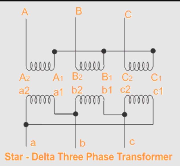
3 SINGLE PHASE TRANSFORMER CONNECTED INTO A STAR DELTA 3∅ GROUP
They are joined by means of common yokes, the top yoke 2, and the bottom yoke 3. The phase windings are arranged on the limbs and are connected into three phase circuit to make a 3∅ transformer.
The first part of the transformer is a 3∅(phase) star connected transformer. While the second part of the transformer is a 3∅(phase) delta connected transformer. Symbolised as ∆
The 3-∅ transformer is obtained by connecting the terminals of three single-phase transformer in such a way as to form a three-phase circuits.


